
A high-reliability frequency converter system is one designed and built to operate continuously with minimal unplanned downtime over its service life. It achieves this through conservative component derating, robust thermal management, redundancy architecture, and rigorous testing to published MTBF standards.
If you are specifying a frequency converter for a data center, airport, hospital, or manufacturing line where unplanned downtime carries high cost or safety consequences, the difference between a standard converter and a high-reliability system is not a marketing label. It is a measurable engineering outcome driven by design decisions at the component, thermal, and system architecture levels. This article explains how reliability is measured, how it is engineered, and what to specify in procurement documents to ensure you get a system that meets your operational requirements.
Key Takeaways
- MTBF (Mean Time Between Failures) for quality industrial frequency converters ranges from 50,000 to 200,000 hours, depending on component selection, derating, and thermal design.
- IGBT modules operated at 60-70% of rated capacity last significantly longer than those pushed to 90% or higher, with every 10°C temperature rise approximately halving component life.
- Redundancy architectures (N+1, 2N, distributed) each offer different availability-to-cost ratios, with 2N achieving 99.999% availability for mission-critical applications.
- The bathtub curve shows that most converter failures occur either early (infant mortality) or late (wear-out), with a long period of constant low failure rate in between.
- Procurement specifications should request MTBF calculation methodology (MIL-HDBK-217 or IEC 61709), not just a single MTBF number, to verify supplier claims.
Need help specifying a high-reliability frequency converter for your critical application? Contact our engineering team for reliability-focused system design and quotation.
What Is a High Reliability Frequency Converter System?
A frequency converter that qualifies as high reliability is engineered from the component level upward to minimize failure probability. The distinction from a standard converter lies in design philosophy: every component operates well below its rated stress levels, every thermal path is calculated and tested, and every failure mode is either eliminated or mitigated through redundancy.
The terms reliability and availability are related but distinct. Reliability is the probability that the converter operates without failure for a specified period. Availability is the fraction of time the converter is operational, accounting for both reliability and repair time. A converter with a 100,000-hour MTBF and a 2-hour average repair time achieves 99.998% availability. The same converter with a 48-hour repair time drops to 99.952% availability. Both metrics matter in procurement decisions.
When Rajesh Menon’s team at a Tier IV data center in Singapore specified their 400Hz power conversion systems, they focused on availability rather than MTBF alone. Their requirement was 99.999% availability, which meant not only high MTBF but also redundant architecture with automatic failover and a maximum 5-minute mean time to repair. The converter vendor who understood both metrics won the contract.
Understanding Reliability Metrics
MTBF: Mean Time Between Failures
MTBF is the average operating time between failures for a repairable system. It is not a guarantee that a specific unit will run for that many hours without failure. It is a statistical measure: if you operate 100 identical converters, the average time between failures across the fleet will approximate the MTBF value.
Industrial frequency converters typically achieve MTBF values in the range of 50,000 to 200,000 hours. A converter rated at 100,000 hours MTBF will experience, on average, one failure every 11.4 years of continuous operation. For a fleet of 10 converters, you can expect roughly one failure per year.
MTBF calculations follow established methodologies:
- MIL-HDBK-217F: The US Department of Defense standard for electronic equipment reliability prediction. Used extensively in military and aerospace applications.
- IEC 61709: The international standard for reliability prediction of electronic components. Preferred in industrial and commercial applications.
- Telcordia SR-332: Originally for telecommunications equipment, now used in data center and IT infrastructure contexts.
The methodology matters because different standards produce different MTBF values for the same hardware. A supplier claiming 150,000 hours MTBF without stating the methodology is making an unverifiable claim.
MTTF: Mean Time To Failure
MTTF applies to non-repairable components such as semiconductor modules, capacitors, and fans. It is the average time until the component fails and must be replaced. For an IGBT (Insulated Gate Bipolar Transistor) module operating at rated conditions, typical MTTF values range from 1 to 3 million hours.
The distinction between MTBF and MTTF is important in system design. The converter system is repairable (MTBF), but individual components within it are not (MTTF). The system MTBF is derived from the component MTTF values and the redundancy configuration.
Availability and the Bathtub Curve
System availability is calculated as:
Availability = MTBF / (MTBF + MTTR)
Where MTTR is Mean Time To Repair. For a system with 100,000-hour MTBF and 4-hour MTTR, availability is 99.996%. To achieve 99.999% availability, you need either much higher MTBF or much lower MTTR, or redundancy that allows continued operation during repair.
The bathtub curve describes failure rate over time for electronic equipment:
- Early failure period (infant mortality): High failure rate in the first few hundred hours due to manufacturing defects. Burn-in testing eliminates these before delivery.
- Useful life period: Constant, low failure rate. This is where the converter spends most of its life. MTBF is calculated during this period.
- Wear-out period: Increasing failure rate as components age. Capacitors dry out, fans wear bearings, and semiconductor junctions degrade.
A well-designed converter spends 15-20 years in the useful life period before wear-out begins. Poor design or aggressive derating shortens this window significantly.
Design Principles for High Reliability
Component Selection and Derating
Derating is the practice of operating components below their rated stress levels. It is the single most impactful design decision for converter reliability.
IGBT module derating: A module rated at 600A and 1200V should operate at no more than 360-420A (60-70% of rated current) and 800V (67% of rated voltage). Operating at 90% of rated current may double the junction temperature and reduce MTTF by an order of magnitude.
Capacitor selection: Film capacitors outperform electrolytic capacitors in reliability-critical applications. Film capacitors have no electrolyte to dry out, no polarity sensitivity, and stable capacitance over temperature. Electrolytic capacitors are cheaper but have a finite lifespan that halves with every 10°C increase in operating temperature.
Connector and terminal quality: Mechanical connections are a common failure point. High-reliability converters use compression terminals rated for the full operating temperature range and vibration environment. Every connection point is a potential failure point.
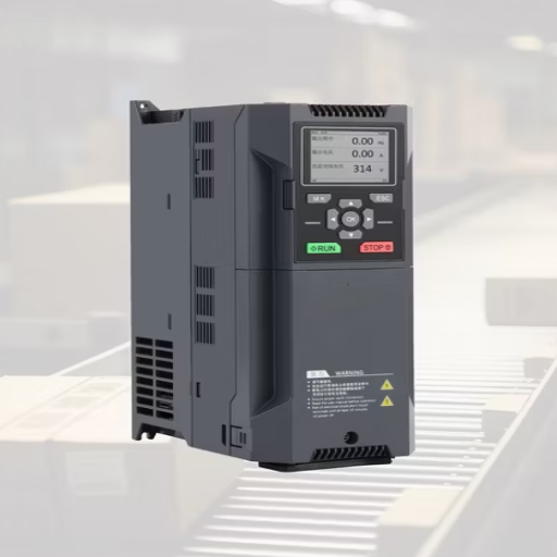
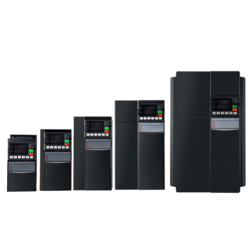
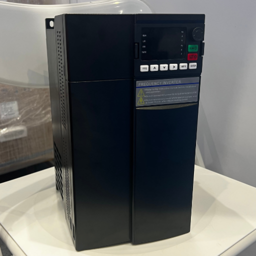
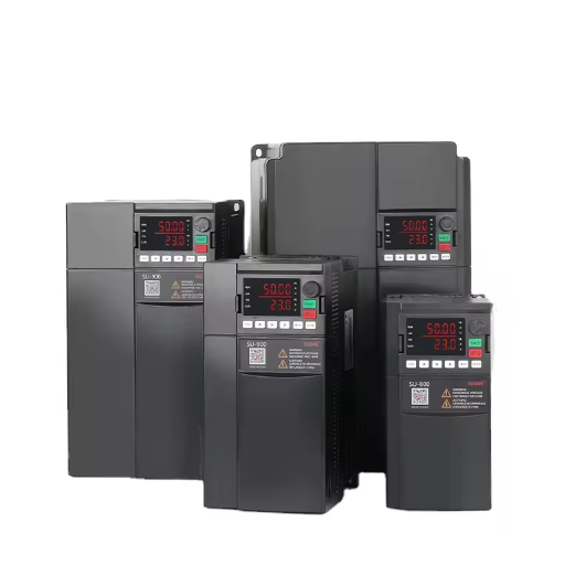
Shandong Electric’s solid state frequency converters use IGBT modules derated to 65% of rated capacity and film capacitors rated for 105°C continuous operation, providing a significant margin in typical 40-50°C operating environments.
Thermal Management
Temperature is the primary accelerator of component degradation. The Arrhenius equation predicts that for every 10°C increase in operating temperature, the failure rate of electronic components approximately doubles.
Effective thermal management includes:
- Forced-air cooling: Fans directing airflow across heat sinks and through the converter enclosure. Properly designed forced-air cooling extends component life 2-3x compared to natural convection.
- Liquid cooling: For high-power converters (500kVA and above), liquid cooling provides more efficient heat removal and more uniform temperature distribution.
- Temperature monitoring: Continuous monitoring of heat sink, ambient, and component temperatures with alarm and shutdown thresholds.
- Environmental specification: Standard industrial converters operate from -10°C to +50°C. Military-specification units extend to -32°C to +55°C for military aircraft ground power supply applications.
Electrical Protection
Power electronics are vulnerable to electrical stress from the supply grid and the load. High-reliability converters incorporate:
- Surge protection: Metal oxide varistors (MOVs) and transient voltage suppressors (TVS) to clamp input voltage spikes from grid switching events.
- Overcurrent protection: Current sensors and fast-acting electronic protection to interrupt fault currents before they damage semiconductor junctions.
- Short circuit protection: Desaturation detection on IGBT modules that triggers shutdown within microseconds of a short circuit event.
- Ground fault detection: Isolation monitoring that detects insulation breakdown before it causes equipment damage or personnel injury.
Mechanical Design
Mechanical reliability is often overlooked in frequency converter design. Vibration, thermal cycling, and environmental contamination cause mechanical failures that are preventable through proper design.
Key mechanical design considerations:
- Vibration resistance: Components secured against vibration levels specified in IEC 60068-2-6 (sinusoidal vibration) or IEC 60068-2-64 (random vibration).
- IP rating: Ingress protection rating matched to the installation environment. IP54 for general industrial, IP65 for dusty or washdown environments.
- Modular design: Field-replaceable modules (power stage, control board, fan assembly) that allow repair without specialized tools or factory return.
Redundancy Architectures
Redundancy allows continued operation when a component or module fails. The choice of redundancy architecture determines system availability, cost, and complexity.
N+1 Redundancy
In an N+1 configuration, one additional converter operates in parallel with the N primary units. If any single converter fails, the remaining N units carry the full load. Automatic load sharing ensures balanced operation.
Advantages: Cost-effective, straightforward implementation, good availability (99.99% with reasonable MTBF and MTTR).
Limitations: The distribution system (bus, breakers, cables) remains a single point of failure. If the common distribution fails, all converters lose load.
2N Redundancy
A 2N configuration provides two completely independent converter systems, each capable of carrying the full load. The load is connected to both systems through an automatic transfer switch (ATS) or static transfer switch (STS).
Advantages: Highest availability (99.999% or better), no single point of failure from converter to load, allows maintenance on one system without affecting the load.
Limitations: Highest cost, most complex, requires two complete power distribution paths.
Distributed Redundancy
In distributed redundancy, multiple converters share the load, and any single converter can fail without loss of service. The difference from N+1 is that the load is distributed across all units, and the system can tolerate multiple failures depending on the configuration.
Advantages: Balanced loading, flexible scaling, good availability with lower cost than 2N.
Limitations: Requires careful load sharing design, more complex protection coordination.
| Architecture | Availability | Relative Cost | Complexity | Best For |
|---|---|---|---|---|
| N (no redundancy) | 99.9% | 1x | Low | Non-critical loads |
| N+1 | 99.99% | 1.3-1.5x | Medium | Industrial, commercial |
| 2N | 99.999% | 2x | High | Mission-critical, data centers |
| Distributed | 99.99% | 1.5-1.8x | High | Data centers, large facilities |
Application-Specific Reliability Requirements
Aviation Ground Power (400Hz)
400Hz ground power systems for airports and military airbases require MIL-STD-704 compliance and high availability because power interruption during aircraft systems testing can corrupt calibration data or damage avionics. Fixed flight line installations typically specify N+1 redundancy with 50,000+ hour MTBF and 4-hour maximum MTTR.
Data Centers
Tier IV data centers require 99.999% availability, which drives 2N redundancy and integrated condition monitoring. The Ponemon Institute estimates data center downtime costs 5,600to5,600to9,000 per minute, making converter reliability a direct financial concern. Condition monitoring with predictive maintenance alerts allows scheduled replacement of aging components before they fail.
Healthcare Facilities
Patient safety requirements under NFPA 99 and IEC 60364-7-710 mandate redundant power for life support systems. Frequency converters in healthcare must maintain power quality within specified limits even during fault conditions. Automatic transfer between redundant systems must be completed within the time tolerance of connected medical equipment.
Industrial Manufacturing
Production line downtime costs vary widely by industry, from 1,000perhourforgeneralmanufacturingto1,000perhourforgeneralmanufacturingto100,000+ per hour for semiconductor fabrication. Reliability requirements should be proportional to downtime cost. A converter serving a non-critical ventilation fan can tolerate lower reliability than one powering a continuous process line.
Priya Sharma’s automotive plant in Chennai experienced three frequency converter failures in one year, each causing 6-8 hours of production line shutdown. After switching to converters with integrated condition monitoring and 80% derated IGBT modules, they achieved zero unplanned converter downtime over the following 24 months. The reliability improvement paid for the converter cost difference in the first quarter.
Maintenance and Lifecycle Management
Preventive Maintenance
Scheduled maintenance extends converter life and prevents unexpected failures. Key activities include:
- Fan replacement: Every 5-7 years, or sooner if vibration or noise increases.
- Filter cleaning or replacement: Every 3-6 months, depending on the environment.
- Connection torque verification: Annual check of all power and control terminal connections.
- Capacitor inspection: Visual inspection for bulging, leaking, or discoloration every 2 years.
Predictive Maintenance and Condition Monitoring
Modern converters can integrate sensors that monitor operating parameters and alert maintenance staff before failure occurs:
- Temperature trending: Gradual increases in heat sink or component temperature indicate degradation.
- Capacitor ESR monitoring: Equivalent series resistance increases as capacitors age.
- Harmonic analysis: Changes in output waveform distortion can indicate component degradation.
- Fan speed monitoring: Decreasing fan speed at constant voltage indicates bearing wear.
Lifecycle Cost Analysis
The initial purchase price of a frequency converter is typically 30-40% of its 10-year total cost of ownership. Energy efficiency, maintenance costs, and downtime costs dominate the lifecycle economics. A converter with 2% higher efficiency saves more in energy costs over 10 years than the entire purchase price difference between a standard and high-reliability unit.
Procurement Specification for Reliability
Technical Requirements to Specify
When issuing a tender for a high reliability frequency converter system, include these parameters:
- MTBF: Minimum hours with stated methodology (MIL-HDBK-217 or IEC 61709). Request the full reliability analysis, not just the headline number.
- Availability: Target percentage with stated MTTR assumption.
- Operating temperature range: Continuous operation specification, not just survival rating.
- Derating requirements: Specify that IGBT modules operate at no more than 70% of rated current and capacitors at no more than 80% of rated voltage.
- Protection features: Surge, overcurrent, short circuit, ground fault, and overtemperature protection.
- EMC compliance: IEC 61000 series for conducted and radiated emissions.
Documentation Requirements
Request the following from bidders:
- Reliability analysis report with MTBF calculation showing component-level data.
- Component list with derating analysis showing stress ratios for all critical components.
- Thermal simulation or test results demonstrating temperature margins.
- Field failure data (if available for existing products) showing actual MTBF versus predicted.
Support Requirements
- Warranty: Minimum 24 months parts and labor.
- MTTR: Maximum repair time commitment with a penalty clause.
- Spare parts availability: 10+ years from date of delivery.
- Technical support response time: 4-hour response during business hours.
Conclusion
A high reliability frequency converter system is the result of deliberate engineering decisions: conservative component derating, robust thermal management, appropriate redundancy architecture, and rigorous testing. The difference between a standard converter and a high reliability system is measurable through MTBF calculations and verifiable through procurement specifications.
When specifying your next frequency converter, request the MTBF methodology, not just the number. Ask for the derating analysis, not just the rating. Demand the thermal test results, not just the operating range. These documents reveal whether the reliability claims are engineering outcomes or marketing statements.
Ready to specify a high reliability frequency converter for your critical application? Contact Shandong Electric for reliability-focused system design, MTBF analysis, and competitive quotations built around your operational requirements.
