
An industrial apparatus requiring power conversion between differing frequencies finds a higher and more suitable application in rotary frequency converters. Notably, these devices are installed in machinery to enable smooth operation across territories with varying power standards, allowing operations to minimize downtime and increase efficiency. This article aims to illuminate the operation of a rotary frequency converter by explaining its underlying principles and providing a few examples of its benefits. Thus, the guide would provide clear and valuable insights, whether you seek to understand the operation of the converters or would like to know about their applications in various industries.
Brief Introduction to Frequency Converter
A frequency converter converts the voltage frequency from one frequency to another in electrical systems, produced in accordance with specific applications and the art of the system. It operates by converting incoming AC (alternating current) power to DC (direct current) and then back to AC power at the desired frequency. It is imperative to ensure compatibility when power systems, both production and utilities, and equipment differ in their frequency standards, such as those found in international operations or non-standard machinery used in industrial operations. Precise control over frequencies by this equipment establishes an environment that optimizes performance, energy efficiency, and durability in applications ranging from industrial machinery to aerospace systems.
What is a Frequency Converter?
A frequency converter is an electrical device meant to change the frequency of an alternating current (AC) to suit the specific power requirements of its particular application under consideration. In essence, the working component converts AC input to DC via a rectifier and then reconverts the DC into AC at the desired output frequency through an inverter. These frequency converters now feature solid-state components and control systems that can generate frequency outputs with precise control and exceptional stability. Their usage is implicated in industries such as aviation, where 400 Hz power is the standard, or in manufacturing industries concerned with machinery that requires non-standard frequency inputs. They also contribute to energy savings by having variable speed control in motor-driven systems, thus preventing unnecessary consumption of electric power and wear and tear on machinery. In addition, the more advanced types feature a monitoring and diagnostic facility that requires less operational intervention and leads to greater predictability for maintenance.
Types of Frequency Converters
| Type | Description | Key Features | Common Applications |
|---|---|---|---|
| Rotary Frequency Converter | Utilizes mechanical rotation to change frequency. | Durable, high output, simple maintenance | Aviation, industrial machinery |
| Static Frequency Converter | Uses solid-state electronics for frequency conversion. | Compact, energy-efficient, low-noise operation | Aerospace, railways, telecommunications |
| Variable Frequency Drive (VFD) | Controls motor speed by varying input frequency. | Energy-efficient, precise control, versatile | HVAC systems, manufacturing, pumps |
| Digital Frequency Converter | Employs microcontrollers for precise digital frequency management. | High accuracy, programmable, advanced diagnostics | Laboratories, test equipment |
| Linear Frequency Converter | Converts linear current without need for rotation. | Low maintenance, stable output | Research, medical instruments |
| Bidirectional Frequency Converter | Supports bidirectional energy flow for varied needs. | Reversible flow, flexible usage, high efficiency | Renewable energy, microgrids |
Overview of Rotary and Static Frequency Converters
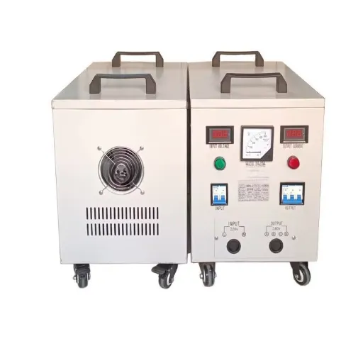
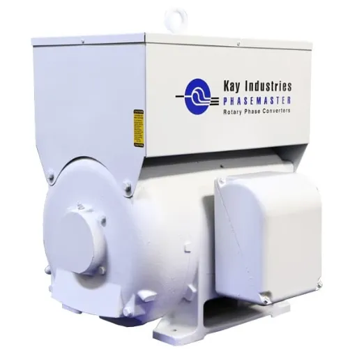
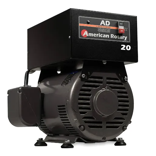
In a rotary frequency converter, the rotating machine does the conversion of electrical power from one frequency to another. Typically, such a converter features an input motor that generates mechanical energy to drive an output generator at the desired frequency. Rotary frequency converters are highly reliable and capable of multiplexing loads, making them suitable for industrial processes such as those found in factories and power plants. It is rugged in design, with low harmonic distortion and capable of providing consistent and enormous power. They are more prone to maintenance, for they have mechanical components and, in some instances, are less efficient when compared to newer methods.
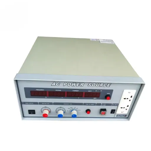
Static frequency converters, in opposition to rotary-type frequency converters, utilize solid-state electronics to achieve frequency conversion without the aid of mechanical moving parts. By using semiconductor devices such as insulated-gate bipolar transistors (IGBTs) or thyristors, static-type frequency converters accurately convert electronic signals to the desired frequency. Due to their compactness, low maintenance requirements, and high energy efficiency, these types of converters are preferred in applications where flexibility and cost-effectiveness are prioritized, such as variable speed drives, renewable energy systems, and aerospace systems. Additionally, static frequency converters offer advanced control and monitoring features, enabling them to adapt more effectively to changes in load conditions. On the downside, static frequency converters may have limited power handling capabilities compared to rotary systems, especially in large-scale industrial operations.
How Rotary Frequency Converters Work?
In rotary frequency conversion methods, mechanical conversion is used to alter the electrical power from one frequency to another. It is essentially a motor-generator set, where the electric motor drives the electrical generator. The motor receives input power at a specific frequency and then rotates the generator to produce output power at a different frequency. This method is best suited for handling large loads while maintaining frequency stability. Since there is a physical separation of motor and generator, the input power set is isolated from the disturbance of the load and the filtering of noise from the output side. Rotary systems are best suited for cases where high power and reliability are required, such as industrial machinery and aerospace equipment.
Basic Principles of Operation
Rotary frequency converters fundamentally operate based on electromagnetic induction and the transmission of rotational energy. The prime mover, or motor, is almost always powered by an AC that mechanically rotates its generator. In this rotation, mechanical energy is converted into electrical energy at a determined frequency. The frequency of the output power depends on the speed of rotation of the motor generator, measured in revolutions per minute. Therefore, the number of poles of the generator is determined by the following relations ( f =( P \cdot n) / 120), where ( f ) is the frequency in Hertz, ( P ) is the number of poles, and ( n ) is the speed of rotation in revolutions per minute (RPM).
High-tech materials with a control system are considered for outstanding performance and efficiency in modern developments. To cite a few examples, you may be aware that good insulation properties almost diminish electric losses. At the same time, well-machined vertices reduce loss through mechanical wear from voltages fed back through the input current after speed detection of the motor, so that any changes of the output frequency caused by the load are eliminated. Such design concepts have made rotary converters indispensable in critical applications where precision and reliability are crucial.
Core Components of Rotary Frequency Converters
Rotary frequency converters comprise various major components that enable them to perform well even under diverse working conditions. Key to the assembly will be the motor-generator set, a generic term referring to an electric motor directly coupled to a generator. Thus, the motor drives the generator to produce an output frequency that differs from that of the input supply. These types tend to use synchronous motors and generators to maintain very close control over frequency, with slight drift, which is crucial for applications requiring high accuracy.
In addition, advanced rotary systems incorporate cooling devices to dissipate heat efficiently and maintain stable operation over extended periods. Bearings and shafts are made of materials that resist wear, with stainless steels, ceramides, and other composites being used to extend the life of these components even at very high rotational speeds. Automatic voltage regulators (AVRs) are installed in the converters to sustain voltage levels and protect the connected equipment from voltage fluctuations.
Technological integration is becoming increasingly embedded in present-day rotary frequency converters, which feature programmable logical controllers (PLCs) for practical applications, including online equipment condition diagnosis, remote monitoring, and system corrections. These benefits enable the converters to operate reliably in demanding situations and comply with the stringent energy-saving and safety directives embedded in international norms.
Differences Between Rotary and Static Frequency Converters
| Parameter | Rotary Frequency Converters | Static Frequency Converters |
|---|---|---|
| Design | Uses rotating mechanical components | Entirely solid-state electronic components |
| Efficiency | Often lower due to mechanical losses | Higher, minimal energy loss |
| Maintenance Requirements | Regular maintenance for moving parts | Minimal maintenance required |
| Durability | Robust, suitable for heavy-duty applications | May degrade faster with heat-sensitive parts |
| Noise Levels | Generates significant mechanical noise | Operates silently |
| Size and Weight | Larger and heavier due to mechanical parts | Compact and lightweight design |
| Initial Cost | Higher upfront investment | Generally lower purchase cost |
| Power Variability Tolerance | Handles power fluctuations effectively | Less tolerant to frequent variations |
| Applications | Industrial, aerospace, maritime sectors | Electronics, data centers, precise equipment |
| Installation Complexity | Requires significant space and expertise | Simpler and less space-intensive |
Benefits of Rotary Frequency Converter
- High Reliability: Frequency converters have proven their durability and ease of maintenance, making them ideal for challenging conditions within the industrial, nautical, and aerospace industries.
- Effective Power Handling: They efficiently handle power fluctuations under varying load circumstances.
- Versatility: These converters cater to heavy equipment and machinery that require specific frequency standards.
- Longevity: They are durable, thereby making them last longer, which minimizes their replacement rate.
- Customizable Output: Rotary systems can be tailored to match the power requirements and frequencies of specific equipment accurately.
Efficiency and Performance
A rotary phase converter is built for maximum efficiency. This means very little energy is lost during operation. The rotary phase converters ensure a smooth and consistent output, which is vital when using sensitive machinery and equipment. Modern rotary converters utilize state-of-the-art components to conserve as much energy as possible, including high-efficiency capacitors and rotors engineered to minimize losses through heating.
The performance criteria for rotary converters describe the ability to maintain steady voltage and consistent frequency, even under peak load conditions. Such sustained credibility ensures smooth operations for both single-phase and three-phase systems. It avoids occurrences that could lead to technical issues with the equipment due to voltage drops or power fluctuations. Recent enhancements in monitoring and control technologies have, however, enhanced this performance by allowing them to operate with real-time adjustments, thereby maintaining accuracy and consistency in a broad spectrum of industrial applications. Currently, it is a well-established solution that serves as a cheaper alternative for various power conversion demands.
Durability in Various Settings
The harshness of the power conversion system is needed to ensure longevity in terms of reliability and performance in varied operational environments. Contemporary power conversions are designed to withstand various conditions, including extreme temperatures, high humidity, and dust exposure, or corrosive agents. For example, advanced conformal coatings are used in conjunction with sealed enclosures to protect internal components from environmental stresses throughout the aging process. Additionally, the harsh environments are tested for thermal cycling and vibration resistance to ensure comfort. According to industry reports, there has been a dire need for materials with very high ingress protection (IP) ratings. In general, high-rated systems tend to exhibit prolonged lifespans, resulting in less need for demanding and costly repairs or replacements. Therefore, the combination of ultra-modern designs and the highest quality standards enables modern power conversion solutions to retain their durability and efficiency even in the most severe environments.
Cost-Effectiveness over Time
One of the primary advantages of modern power conversion systems is their long-term cost-effectiveness. These systems utilize new materials and designs to achieve significant energy loss reduction and lower operational costs over an extended period. Circumstantial information suggests that these high-efficiency power conversion entities are said to reduce 30% of wasted energy, whose benefits are expected to trickle down in the form of cost savings to major energy-consuming industries. In addition to the reduction, there is also a low maintenance cost due to the durability of its components. Through means of economic results, scalability, and upgradability of future technological purchases, they continue to strengthen the long-term value of their investment in state-of-the-art power conversion solutions.
Common Applications Across Industries
- Manufacturing: In factories, these advanced systems optimize energy use, ensuring machinery operates smoothly without downtime and energy waste.
- Renewable Energy: In connection with producing wind and solar power, these solutions convert and stabilize energy efficiently for grid integration.
- Data Centers: High-efficiency power conversion reduces energy consumption while supporting critical infrastructures and lowering overall operating costs.
- Transportation: Advanced conversion technology fuels performance and conserves energy in electrified rail systems and electric vehicle charging stations.
- Healthcare: Utilize medical equipment that benefits from precise power delivery and continuous operation, essential for patient safety and care.
Manufacturing Sector Use Cases
Modern manufacturing stands at the crossroads where power conversion technology efficiently supports the smooth operation of varied industrial processes. State-of-the-art converters supply energy to automation machinery, robotics, CNC machines, and assembly lines with high consistency and efficiency, assuring unimpeded precision and output. Next, energy reclamation systems utilizing regenerative braking in production equipment are employed in industrial sites to efficiently reduce energy waste and operational costs. Likewise, industrial electricity has undergone revolutionary changes in its various forms, as its infrastructure has served as a primary testbed for innovative energy sources. Consequently, existing systems are becoming increasingly advanced.
Aerospace Industry Applications
Lightweight Composite Materials
It is worth noting that the advancement towards introducing new composite materials in this case may have helped decrease the weight of an aircraft by up to 20-40%, thereby favouring fuel savings and minimizing the release of hazardous greenhouse gases. As an illustration, CFRPs are present in 50% of the structures of the Boeing 787 Dreamliner, a fact that helps reduce fuel consumption by 20% compared to similar aircraft.
Electric and Hybrid Propulsion Systems
The invention of electric and hybrid electric propulsion small jet engines marks a significant breakthrough toward capable new-age aviation. Hypothetically, Airbus has even sketched a future commercial vehicle known as the E-fan X —a hybrid electric demonstrator that is estimated to reduce fuel consumption by 30%. These systems are underpinned by evolutions in high-energy-density lithium-ion batteries and supercapacitors.
Precision Manufacturing and Additive Manufacturing (AM)
To produce lightweight objects and those with extreme complexity, the aerospace industry has adapted the use of laser sintering or 3D printing, along with other processes. In fact, General Electric Aviation uses AM in its thermoset thermoplastic fuel nozzles for the LEAP engine, which decreases the weight of the part by 25% and increases its service life. This trend favors the aeroplane industry in terms of its traditional production costs and increasing its effectiveness.
Aerodynamic Optimization
The economic benefits of upgrades such as winglets and laminar flow methods are evident due to their impact on improving performance, aside from higher aerodynamic efficiency and lower drag. According to research, such savings can reach 4% to 6% of fuel, thanks to these advancements, resulting in savings over the aircraft’s lifetime, whether during construction or maintenance of the airplane.
Real-Time Data Analytics and IoT Technologies
Currently, aircraft are enhanced by novel technologies, such as the use of Internet of Things (IoT) equipment linked to sensors for the real-time transmission of performance-based data. This prevents malfunctions and decreases operational malfunctions up to 30%. The application of big data, coupled with analytics, enables operationally efficient planning of dashboards, fuel consumption monitoring, and enhancement of air traffic coordination.
Renewable and Sustainable Aviation Fuels (SAFs)
Sustainable aviation fuels (SAFs), which originate from sources such as crop residues, algae, and others, have been found to reduce life-cycle carbon emissions by up to 80% compared to traditional jet fuel. Airlines, as far as SAFs are concerned, are more towards these renewable feeds.
Renewable Energy Solutions
The increased reliance of aerospace improvement methodologies on green technologies has become an area with widespread advancements as regards both sustainability and performance efficiency. One of such technologies is the incorporation of solar power in long-range and long-operating unmanned aerial vehicles (UAVs) and satellite applications. Increases in the efficiency of solar cell modules, such as the development of quantum well cells, which convert over 40% of sunlight into electricity, become the defining factor for the acceptance of solar energy in demanding aerospace applications. Furthermore, hydrogen fuel cells are introduced as a step towards a more environmentally friendly and energy-efficient propulsion system. These work by converting chemical energy into electric energy, which enriches reactions in water only, making them ideal for mitigating carbon gas emissions.
Indeed, the wind sector, aside from traditional aerospace, has been instrumental in the development of hybrids and on-the-ground infrastructure. This is achieved mainly through activities such as the processing of various aerospace elements using renewable materials, rather than direct implementation in aerospace operations. Focusing on the integration of different renewable energy systems in future aircraft and ground support technologies can be termed to have great potential. These also do not depend on fuel as much as they did before – fuel that is likely to run out, without ignoring the fact of the ecological damage – operating so that the systems could be calledable for the stabilization of the environmental condition over a long period a matter of aerospace engineering.
Practical Tips for Selecting the Right Converter
- Assess Your Power Requirements: Determine the current and voltage levels your system needs to operate correctly. It is necessary to use the right converter, particularly when the condition is at its peak, and one’s goal is to optimize and increase the system’s lifespan simultaneously.
- Prioritize Efficiency: Find a converter that offers high efficiency (watts/watt-hours) to minimize power loss and emit the least heat possible. High efficiency also enhances the achievement of the system’s objectives, thereby enabling the achievement of the goals within lower expenditures.
- Consider Size and Weight Constraints: In fields such as aerospace and portable appliances, where space management plays a crucial role in device design, emphasis should be placed on developing compact, lightweight designs that accommodate the necessary capacity.
- Evaluate Input and Output Flexibility: It is worth paying attention to whether the given converter has input supply voltage and output signal values that fall within the allowable values for your equipment. Some converters even provide the capability to adjust the level of the output signal as a feature.
- Verify Reliability and Safety Standards: Ensure the converter is designed in accordance with prevailing industry safety standards (e.g., CE, UL) and confirm that the product provides over–voltage, over-current, and thermal protection at all times.
- Analyze Environmental Compatibility: Make sure whether the converter is suited for the extreme conditions within your application as well, such as high temperatures, wet areas, shock areas, or aggressive use.
Assessing Load Requirements
An essential aspect of this step is defining the power of the load, measured in watts or VA, in relation to the instantaneous rating of the load, the steady-state load, and possibly the inrush currents during the load’s startup. Under no circumstances should the load exceed the converter’s rating. The counterpart of load characteristics must be the behavior of the load and its type, whether resistive, inductive, or capacitive, because input power converters are characterized by the different possible ways of operating they provide. For example, for inductive loads such as motors, larger converters with increased surge capabilities may need to be designed to accommodate the large initial current draw. Another critical point is the efficiency of both the converter itself and the load. When discussing the effectiveness of wills, it is usually in the range of 85% to 95%. Efficiency losses are calculated to prevent making components too small, due to inefficiencies associated with component selection. Inquire about the operational limitations in terms of the output voltage and current to ensure that the connected equipment will work and that risks of syncope or premature failure would not be related to this factor.
Understanding Operational Environments
Complicated operational conditions play a significant role in the proper functioning and lifespan of machines and plants. For example, the designer or user of any installation must take into account the following factors: temperature and its uniformity within the equipment, humidity, altitude, and air impurities. This is because at high ambient temperatures, the working life of the components may be shortened due to accelerated degradation. Meanwhile, the presence of excessive humidity, when it comes into contact with the metallic surfaces, causes corrosion and reduces insulation resistance. Furthermore, higher altitudes necessitate mechanisms that accommodate variations in effective convective heat transfer, which changes due to lower air density. Appreciating the forces of nature in a given place enables the design of the proper materials, enclosures, and components, as is the case with IP protection, thermal management, and other industry norms. Customizing design solutions to account for weather and other space-related variables will not only enhance performance and longevity but also reduce the likelihood of sudden and unplanned failures or maintenance issues.
Evaluating Long-Term Cost-Effectiveness
When evaluating the long-term cost-effectiveness, the pemysl must consider both initial investments and the cost of operations over the system’s duration. This involves factoring in elements such as the object’s ability to conserve power, the period during which the parts can be used before they need to be replaced, and the frequency of repairs required for these parts. For example, modular systems are more cost-effective in the long run compared to non-modular systems due to their simple process for parts replacement and upgrading. Additionally, recent developments in techniques such as energy-saving drives, as well as preventive and predictive maintenance practices, have been beneficial in reducing operating costs. In any case, the rich and meaningful application of data leads to the use of real-time performance measures and the analysis of failure rates to enable the prediction of inevitable cost consequences. This method enables the selection of optimal choices that yield the best financial results in a state of reliability and sustainability.
Reference Sources
-
Development of a Rotary Thermomagnetic Motor for Thermal Energy Conversion
- Summary: This study focuses on the development of a rotary thermomagnetic motor, which leverages thermal energy for power conversion. The research builds on foundational work in thermomagnetic principles and explores the integration of rotary mechanisms for efficient energy conversion.
-
- Summary: This research investigates the stability of electric traction power systems, focusing on low-frequency interactions between rail vehicles and rotary frequency converters. It identifies oscillation issues and proposes solutions to improve system stability.
Frequently Asked Questions (FAQs)
Q: What is a rotary frequency converter and how does it work?
A: Rotary frequency converters, a rotary power converter as known in our industry, is a device that transforms power from one frequency to another, usually for the most common 50 Hz or 60 Hz power systems. I.e., the output frequency is less than the input frequency if vice versa. This is through a rotary machine, comprising an OD induction motor and an OS synchronous generator. The latter takes an input AC source and tries to produce an AC output of the same frequency. When in use, the mechanical energy from the drive to the generator is a function of the controlled speed of the generator, which is necessary for regulating the required frequency.
Q: What are the benefits of rotary frequency converters compared to static frequency converters?
A: There are numerous advantages to using rotary frequency converters as opposed to solid-state frequency converters. Among these are the high-power capabilities of the rotary units in comparison to the solid-state devices. A rotary unit is beneficial in situations where there is a sudden surge in motor load, such as during a starting event, as is the case when a machine is being turned on. In addition, factors related to mechanical engineering address this, including the energy output for a given AC power and deviations in voltage and frequency values. Rotary converters, on the other hand, can work with adjustable voltages.
Q: How can a rotary frequency converter convert 50Hz to 60Hz power?
A: In its construction, a rotary frequency converter can change 50Hz power to 60Hz power thanks to a unique positioning of a synchronous generator and an induction motor. When a 50Hz alternating current is presented to the rotary converter, the device uses mechanical energy to propel the generator at a rate that achieves a 60Hz output. This is accomplished through changing the speed of the rotating components while the motor is in operation. This ensures that the modification from one frequency to another is done without any excessive losses and without altering the 60Hz power.
Q: What types of applications benefit from rotary frequency converters?
A: Rotary frequency converters are commonly found in many applications, such as heavy-duty industrial machinery, military hardware, and aerodynamic equipment that require simultaneous operation with 50Hz and 60Hz power. The AC frequency they serve makes them quite valuable for logistically located facilities, specifying 400Hz for which rotary frequency converters are employed. These days, in centers having varied power systems, converters have become indispensable as they can generate AC power from mechanical energy. They can also be used in many other instances where the loss of electric power can result in significant economic loss, such as data centers, key installations, and similar facilities.
