
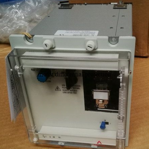
Motor differential protection, designated by ANSI device number 87M, compares the current entering and leaving a motor to detect internal faults such as stator winding failures that overcurrent relays cannot sense. It is typically specified for medium voltage motors above 750 kW where the cost of motor damage or production loss justifies the additional protection investment.
A petrochemical plant in Southeast Asia operated a 3,500 kW, 6.6 kV compressor motor without differential protection. In March 2025, a turn-to-turn fault developed in the stator winding. The motor’s thermal overload relay (49) did not operate because the fault current was only 180% of full-load current, well below the phase overcurrent pickup. The ground fault relay (51N) also missed the fault because it was a phase-to-phase internal fault with minimal ground current. The motor continued running for 47 minutes until the winding completely failed. The repair required a complete rewind costing $280,000 and 10 days of downtime. A microprocessor-based 87M relay with 15% pickup would have cleared the fault in 25 milliseconds, limiting damage to a few winding turns repairable in 8 hours.
This guide explains when motor differential protection is necessary, how to select current transformers (CTs), calculate settings, and choose between percentage and high-impedance schemes. It also covers VFD-fed motor considerations and real cost benchmarks to help you make informed specification decisions.
Key Takeaways
- Differential protection (87M) detects internal motor faults that overcurrent relays (50/51) cannot sense, with typical operating times of 15-30 milliseconds
- Specify 87M for motors typically above 750 kW (1,000 HP) at medium voltage, or for any critical motor where outage cost exceeds protection cost
- CTs must be matched in ratio, accuracy class, and construction; typical accuracy class is 5P or 10P with adequate knee-point voltage
- Percentage differential relays are preferred for most motor applications due to stability during starting inrush and tolerance for CT mismatch
- Typical 87M settings include pickup at 10-20% of motor rated current, slope at 20-30%, and second harmonic restraint at 15-20%
- VFD-fed motors require CTs on the line side only; inverter switching noise can cause nuisance trips if CTs are placed on the motor side
- Adding differential protection to a motor protection scheme costs approximately 3,000−3,000−8,000 for the relay plus 1,500−1,500−4,000 for matched CTs
What Is Motor Differential Protection?
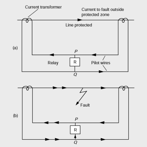
Motor differential protection is a current-comparison scheme that measures the current entering the motor and compares it to the current leaving the motor. Under normal conditions, these two currents are equal. When an internal fault occurs, such as a stator winding short, the currents become unbalanced. The differential relay detects this imbalance and trips the circuit breaker to isolate the fault.
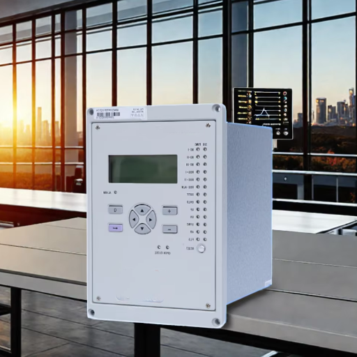
The ANSI device number for this function is 87M, where 87 designates differential protection and M specifies rotating machinery. Modern 87M relays are microprocessor-based units that offer percentage bias characteristics, harmonic restraint, and high-set instantaneous elements. These features improve both stability during external faults and sensitivity for internal faults.
What 87M Protects Against
Differential protection is specifically designed to detect internal faults within the motor windings and connections. It responds to phase-to-phase faults, turn-to-turn faults, and some ground faults that occur within the protected zone. However, it does not protect against bearing failures, rotor bar breakage, or overload conditions. These require other protection functions such as thermal overload (49), vibration monitoring, or negative sequence (46) relays.
Why Overcurrent Protection Is Insufficient for Large Motors
Phase overcurrent relays (50/51) are set above motor starting current to avoid nuisance trips. For a typical medium voltage motor with 6 times full-load current during starting, the overcurrent pickup is usually set at 115-125% of locked-rotor current. An internal turn-to-turn fault may produce only 150-200% of full-load current, which is well below the overcurrent pickup threshold. The motor can sustain this level of current for minutes or hours, causing catastrophic damage before the overcurrent relay finally operates. Differential protection, with pickup settings of 10-20% of rated current, detects these faults immediately.
When to Specify Motor Differential Protection
Not every motor needs differential protection. The decision depends on motor size, voltage level, application criticality, and economic factors. Adding 87M increases project cost by 5,000−5,000−15,000 when relay, CTs, engineering, and commissioning are included. The specification is justified when the protected motor’s value or the cost of unplanned downtime exceeds this incremental investment.
Motor Size Thresholds by Voltage
IEEE C37.96 provides general guidance for when to consider differential protection based on motor horsepower and voltage. For low voltage motors below 1 kV, differential protection is rarely justified below 500 kW because motor replacement costs are relatively low and overcurrent protection is usually adequate.
For medium voltage motors in the 1 kV to 7.2 kV range, engineers typically specify 87M for motors above 750 kW. This threshold balances protection cost against the increasing value of larger motors and their greater impact on production continuity.
For high voltage motors above 7.2 kV, differential protection is commonly applied to motors above 1,500 kW. At these voltage and power levels, motor replacement costs frequently exceed $200,000, and specialized construction means long lead times for replacements.
| Voltage Level | Typical Differential Protection Threshold |
|---|---|
| Low Voltage (<1 kV) | Rarely below 500 kW |
| Medium Voltage (1-7.2 kV) | Above 750 kW |
| High Voltage (>7.2 kV) | Above 1,500 kW |
Criticality and Economic Factors
Continuous process industries such as petrochemical refining, power generation, and water treatment specify differential protection for critical motors regardless of size. In these applications, a single motor trip can shut down an entire production train. The lost production value often exceeds $50,000 per hour.
Motors with custom construction or long manufacturing lead times also justify 87M protection. A specialized synchronous motor with a 26-week lead time represents both a capital investment and a schedule risk that differential protection helps mitigate.
The cost-benefit framework is straightforward. If the sum of motor replacement cost plus estimated production losses during repair exceeds three to five times the differential protection installation cost, specification is economically justified.
Industry-Specific Recommendations
API 541 and API 547 standards for petrochemical motors often require differential protection for form-wound motors above certain ratings. Power plant auxiliary motor protection standards typically specify 87M for boiler feed pump motors, induced draft fans, and circulating water pumps. For digital substations with IEC 61850 process bus architecture, differential protection integrates into the station-wide protection and control system through GOOSE messaging.
Want to understand how motor differential protection fits into the complete protection scheme? Read our complete guide to medium voltage motor protection and control for a system-level overview.
CT Selection for Motor Differential Protection
Current transformer selection is the most critical specification task for motor differential protection. Incorrect CTs cause nuisance trips, reduce sensitivity, or render the protection inoperable. The selection process involves determining CT location, ratio, accuracy class, and matching requirements.
CT Location and Configuration
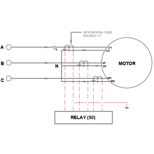
Motor differential protection uses one of two CT configurations. The six-CT scheme places phase CTs on both the line side and the neutral end of the motor. This configuration provides the most comprehensive protection because it covers the entire winding and both connection points. It is the standard choice for large, critical motors.
The two-CT or four-CT scheme uses line-side CTs combined with neutral-end CTs. This approach reduces CT count and wiring complexity. It is suitable for smaller motors or applications where space constraints limit CT installation. However, it may leave some portions of the winding less completely protected.
CT Ratio Selection
The CT primary current rating is typically selected at 1.5 times the motor full-load current. This ensures the CT operates in its linear region during normal load while accommodating motor overload conditions. For example, a motor with 210 A full-load current would use 300/1 A CTs.
All CTs in a differential scheme must have identical ratios. A mismatch in ratio produces a standing differential current that can cause false trips or desensitize the relay. Secondary currents must match within 1% for high-impedance schemes and within 5% for percentage differential schemes.
Accuracy Class and Knee-Point Voltage
Protection-class CTs are required for differential applications. Standard metering CTs with class 0.5 accuracy are unsuitable because they saturate at low multiples of rated current. Differential protection CTs should be class 5P or 10P, or Class X (PX) for high-impedance applications.
A consulting engineer specifying a 1,500 kW pump motor selected standard metering-class CTs for the differential scheme to save 800.Duringcommissioning,therelaynuisance−trippedthreetimesduringnormalstarting.InvestigationrevealedthemeteringCTssaturatedat3timesratedcurrent,wellbelowthe6timesstartingcurrent.TheengineerreplacedtheCTswith5P10protection−classCTs.ThetotalcostofreplacementCTs,re−wiring,repeatedcommissioning,anddelayedplantstartupexceeded800.Duringcommissioning,therelaynuisance−trippedthreetimesduringnormalstarting.InvestigationrevealedthemeteringCTssaturatedat3timesratedcurrent,wellbelowthe6timesstartingcurrent.TheengineerreplacedtheCTswith5P10protection−classCTs.ThetotalcostofreplacementCTs,re−wiring,repeatedcommissioning,anddelayedplantstartupexceeded18,000.
For percentage differential schemes, 5P10 or 10P10 CTs are typically adequate. The “10” in 5P10 means the composite error does not exceed 5% at 10 times rated current. For high-impedance schemes, Class X (PX) CTs with defined knee-point voltage are required. The knee-point voltage must satisfy:
Vk >= 2 x Ifault_max x (RCT + RL + Rrelay)
Where RCT is the CT secondary winding resistance, RL is the lead resistance, and Rrelay is the relay burden.
CT Matching Requirements
Matched CTs are essential for differential stability. All CTs in the scheme should be the same manufacturer, model, ratio, and accuracy class. During commissioning, verify that magnetization curves are within 5% of each other. Even small differences in CT construction can produce differential current during through-faults or motor starting.
Percentage Differential vs High-Impedance Schemes
Two principal schemes exist for motor differential protection: percentage (biased) differential and high-impedance differential. Each has distinct advantages, limitations, and appropriate applications.
Percentage (Biased) Differential Relay
The percentage differential relay compares the differential current to the through-current. The relay operates only when differential current exceeds a defined percentage of the through-current. This percentage is called the slope, and it provides restraint against external faults and CT mismatch.
Typical settings for a percentage differential relay include a pickup threshold of 10-20% of motor rated current, a first slope of 20% up to 2 times rated current, and a second slope of 40% above that level. Second harmonic restraint at 15-20% blocks operation during motor inrush, when second harmonic content can reach 15-25% of fundamental current.
The primary advantage of percentage differential is tolerance for CT mismatch. It remains stable during motor starting even when CTs have minor differences in ratio or characteristics. This makes it the preferred choice for most industrial motor applications.
High-Impedance Differential Relay
The high-impedance scheme operates on a different principle. All CT secondaries are connected in parallel across a high-impedance relay element. During external faults, CT saturation causes unequal secondary currents that circulate through the CT windings rather than flowing through the relay. During internal faults, the CTs drive current through the relay element, producing a voltage that causes operation.
High-impedance relays require Class X (PX) CTs with closely matched characteristics and adequate knee-point voltage. A voltage-limiting device, typically a Metrosil or varistor, protects the relay and CT insulation from excessive voltage during internal faults.
The advantage of high-impedance differential is absolute stability for external faults and extremely fast operating times, often below 20 milliseconds. It is best suited for motors with very high starting current or applications where CT saturation risk is significant.
Decision Matrix
| Factor | Percentage Differential | High-Impedance Differential |
|---|---|---|
| CT requirements | 5P/10P, moderate matching | Class X (PX), strict matching |
| CT cost | 1,500−1,500−4,000 per set | 2,500−2,500−6,000 per set |
| Tolerance for CT mismatch | 5-10% | Less than 2% |
| Stability during starting | Good with harmonic restraint | Excellent |
| Operating speed | 20-40 ms | 15-25 ms |
| Best application | Most industrial motors | Very large or critical motors |
For the majority of medium voltage industrial motors, percentage differential provides the best balance of performance, cost, and commissioning simplicity.
Need help selecting the right protection scheme for your motor application? Our engineering team can review your specifications and recommend the optimal configuration. Contact our protection engineers for project support.
87M Setting Calculation: Worked Example
The following example demonstrates the complete setting calculation for a 2,000 kW, 6.6 kV induction motor using a percentage differential relay.
Motor Data
- Power: 2,000 kW
- Voltage: 6.6 kV, 3-phase
- Frequency: 50 Hz
- Full-load current: 210 A
- Starting current: 6 x FLC = 1,260 A
- Locked-rotor withstand time: 12 seconds
CT Selection
- Ratio: 300/1 A
- Accuracy class: 5P10
- Knee-point voltage: 250 V
- Secondary winding resistance: 3.5 ohms
Relay Settings
Pickup (Id>): Set at 15% of motor rated current.
- Id> = 0.15 x (210 A / 300) = 0.105 A secondary
- Round to 0.11 A for practical setting
Slope 1: 20% up to Is1 = 2.0 times rated current.
- This provides restraint for normal load variations and minor CT mismatch
Slope 2: 40% above Is1 = 2.0 times rated current.
- Increased restraint for high through-currents during starting
Second Harmonic Restraint: 15%.
- Blocks relay operation when second harmonic exceeds 15% of fundamental
Instantaneous High-Set: 8.0 times rated current, unrestrained.
- Provides fast clearing for severe internal faults without slope delay
Stability Verification During Starting
During motor starting, the through-current is 1,260 A primary, which equals 4.2 A secondary. With 5% CT mismatch, the differential current is 0.21 A. At 4.2 A through-current with a 20% slope, the relay requires 0.84 A differential current to operate. Since 0.21 A is less than 0.84 A, the relay remains stable during starting.
Sensitivity Verification for Internal Fault
For a minimum internal fault current of 500 A primary (1.67 A secondary), the operating threshold at this through-current level is 0.33 A. Since 1.67 A exceeds 0.33 A, the relay operates sensitively for this fault level. This sensitivity is approximately 16 times better than a typical overcurrent relay set at 1,200 A pickup.
For more detail on protection relay settings across all ANSI device numbers, see our practical guide to motor protection relay settings.
Differential Protection for VFD-Fed Motors
Variable frequency drives introduce unique challenges for motor differential protection. The PWM output from the inverter creates high-frequency switching transients that can affect CT performance and relay operation.
CT Placement: Line Side vs Motor Side
For VFD-fed motors, CTs should be placed on the line side of the inverter, between the supply and the VFD input. Placing CTs on the motor side, between the VFD output and the motor, exposes them to PWM switching noise. This noise can induce false differential currents that cause nuisance trips.
A water treatment facility installed differential protection on a 1,000 kW VFD-fed pump with CTs on both the line and motor sides of the inverter. During commissioning, the 87M relay tripped intermittently at random intervals during normal operation. The protection engineer discovered that PWM switching edges induced high-frequency currents in the motor-side CTs, creating a false differential signal of 8-12% of pickup. Relocating all CTs to the line side of the VFD eliminated the nuisance trips.
Harmonic Considerations
VFD output contains significant harmonic content that differs from the harmonic signature of direct-on-line motor starting. Second harmonic restraint, which is effective for blocking inrush during DOL starting, may not reliably block inverter harmonics. Third harmonic circulating current in the motor neutral can also create differential signals in certain CT configurations.
Modern microprocessor relays address these challenges through digital filtering and frequency-tracking algorithms. Some relays offer specific VFD application settings that modify the harmonic restraint and pickup thresholds for inverter-fed applications.
Relay Selection for VFD Applications
When specifying differential protection for VFD-fed motors, select a relay with frequency-tracking capability and adjustable digital filters. The relay should operate correctly across the VFD output frequency range, typically 5-60 Hz or wider for specialized applications. Verify with the manufacturer that the relay is rated for PWM environments.
For a deeper understanding of VFD harmonics and their impact on protection systems, refer to our MV drive power quality guide.
Installation and Commissioning Best Practices
Proper commissioning ensures that differential protection operates correctly for both internal faults and external disturbances. Skipping commissioning tests is a common cause of misoperation in service.
Wiring and Polarity Verification
Verify CT polarity before energizing the motor. Incorrect polarity produces a standing differential current equal to twice the load current, causing immediate tripping. Use a primary injection test set to inject current through each CT and verify that secondary currents match expected magnitude and phase relationship.
Commissioning Tests
Perform three essential tests during commissioning. First, conduct a stability test by injecting through-current equivalent to motor starting current and verifying that the relay remains stable. Second, perform a sensitivity test by simulating an internal fault at the minimum fault level and confirming relay operation. Third, verify pickup accuracy by injecting current at the set pickup threshold and measuring actual operate time.
Maintenance and Periodic Verification
IEEE recommends testing protective relays every two to four years depending on criticality. For differential protection, the maintenance program should include CT magnetization curve verification, wiring insulation resistance testing, and relay setting audit. Any motor rewind, cable replacement, or CT replacement requires re-commissioning of the differential scheme.
Cost Considerations and Specification
Understanding the incremental cost of differential protection helps justify the investment to project stakeholders and compare alternatives accurately.
Differential Protection Relay Cost Ranges
Basic electromechanical differential relays cost 2,000−2,000−4,000 but offer limited functionality and no harmonic restraint. Microprocessor-based single-function 87M relays range from 3,000−3,000−6,000. Multifunction motor protection relays that include 87M along with thermal overload, overcurrent, ground fault, and negative sequence functions cost 5,000−5,000−10,000. The multifunction approach reduces panel space and wiring complexity.
CT Incremental Cost
Matched protection-class CTs for percentage differential schemes cost 1,500−1,500−4,000 per set of six. Class X (PX) CTs for high-impedance schemes cost 2,500−2,500−6,000 per set due to tighter manufacturing tolerances and defined knee-point voltage requirements.
Engineering and Commissioning
Protection study and setting calculation by a qualified engineer costs 2,000−2,000−5,000 depending on motor complexity. Commissioning and primary injection testing adds 1,500−1,500−3,000. For a typical medium voltage motor, the total incremental cost of adding differential protection is 7,000−7,000−17,000.
When compared to motor replacement costs of 150,000−150,000−500,000 for large MV motors, plus production losses of 10,000−10,000−100,000 per hour in continuous processes, the protection investment pays for itself if it prevents just one major fault.
Frequently Asked Questions
What is the ANSI device number for motor differential protection?
The ANSI device number is 87M, where 87 designates differential protection and M specifies rotating machinery.
At what motor size should differential protection be specified?
For medium voltage motors (1-7.2 kV), specify 87M for motors above approximately 750 kW. For high voltage motors above 7.2 kV, differential protection is commonly applied above 1,500 kW. Critical motors in continuous process industries may justify differential protection at smaller sizes.
Can differential protection detect rotor faults?
No. Differential protection detects stator winding faults and connection faults within the protected zone. Rotor faults, bearing failures, and mechanical issues require other monitoring methods such as vibration analysis, rotor flux monitoring, or negative sequence protection.
What is the difference between percentage and high-impedance differential?
Percentage differential compares differential current to through-current using a slope characteristic. It tolerates moderate CT mismatch and is preferred for most industrial motors. High-impedance differential uses a voltage-operated relay across paralleled CT secondaries. It offers absolute stability for external faults but requires closely matched Class X CTs.
Does a VFD-fed motor need differential protection?
VFD-fed motors benefit from differential protection if they are large or critical. However, CT placement is essential. Install CTs on the line side of the VFD, not the motor side, to avoid PWM switching noise. Select a relay with frequency-tracking and digital filtering for VFD applications.
How do you test motor differential protection during commissioning?
Commissioning requires three tests: a stability test with through-current at starting level, a sensitivity test with simulated internal fault current, and a pickup verification test. Primary injection testing verifies CT polarity and ratio. Secondary injection testing verifies relay settings and operating characteristics.
What CT accuracy class is required for motor differential protection?
Use protection-class CTs rated 5P or 10P for percentage differential schemes. For high-impedance schemes, use Class X (PX) CTs with defined knee-point voltage. Standard metering CTs with class 0.5 or 1.0 accuracy are unsuitable because they saturate at low multiples of rated current.
Conclusion
Motor differential protection is the last line of defense for large industrial motors. When specified correctly with matched CTs and properly calculated settings, 87M detects internal faults that no other protection function can sense. The investment of 7,000−7,000−17,000 for a typical installation is modest compared to the 150,000−150,000−500,000 cost of replacing a large MV motor and the production losses that accompany unplanned outages.
The specification process requires attention to CT selection, scheme choice, setting calculation, and commissioning verification. Percentage differential relays suit most applications, while high-impedance schemes excel for the largest and most critical motors. VFD-fed applications require special consideration for CT placement and relay selection.
For engineers designing medium voltage motor protection and control systems, differential protection should be part of a comprehensive protection strategy that includes thermal overload, overcurrent, ground fault, and negative sequence functions. Each protection element addresses a different failure mode, and together they provide complete motor coverage.
Ready to protect your critical motors? Our engineering team provides technical consultation for motor power systems, protection integration, and custom frequency converter solutions. Contact Shandong Electric to discuss your project requirements.
