
An airport 400Hz power supply system transforms standard grid electricity into the precise 400Hz, 115V/200V power that aircraft need while parked at the gate. Designing this infrastructure requires choosing between centralized and distributed architectures, sizing cables for voltage drop, balancing loads across gates, and planning for the electrification of all ground support equipment.
Most airport planners start with a simple question: how do we get power from the electrical room to the aircraft? But the real engineering challenge runs much deeper. Cable distances, diversity factors, redundancy requirements, pit systems, and integration with pre-conditioned air all affect the final design. Get the architecture wrong and you face voltage drop issues at remote gates, overloaded distribution boards during peak hours, or civil works costs that blow the project budget.
This guide walks through the complete design process for an airport 400Hz power supply. You will learn how to choose between centralized and distributed systems, size cables and converters, budget power per gate, and future-proof your infrastructure for electric GSE.
Puntos Clave
- Centralized 400Hz systems suit large new-build airports with short cable runs; distributed point-of-use systems win for retrofits and medium airports due to lower civil costs and modular expansion.
- Voltage drop at 400Hz is 20-25% lower than at 50Hz for the same cable, but aircraft tolerance is tight (plus or minus 3V), so cable sizing remains critical for runs over 50 meters.
- Gate diversity factors of 0.6-0.7 mean a 6-gate system rarely draws more than 60-70% of the sum of individual gate ratings, allowing smaller centralized converters than simple addition suggests.
- A fully electrified wide-body gate may need 250-350 kVA total (GPU + PCA + electric pushback/cargo), so 400Hz infrastructure must be sized for the full electric GSE roadmap.
- Pop-up pit systems cost 80,000-80,000-150,000 per gate including civil works, while overhead cable systems cost 15,000-15,000-30,000 per gate, making the pit vs overhead decision a major budget factor.
Centralized vs Distributed Architecture
The Centralized Model
In a centralized airport 400Hz power supply system, one or more large static converters are installed in a dedicated electrical room. These units feed 400Hz power through a distribution switchboard to multiple gates via dedicated cable runs. A typical configuration uses a 500 kVA or 1,000 kVA converter feeding 6-12 gates through a centralized distribution system.
The advantages are real. Large converters achieve higher efficiency (95-97% for units above 500 kVA) and lower cost per kVA than smaller units. Maintenance is concentrated in one climate-controlled room. Spare parts inventory is simplified. And the system looks elegant on paper.
The drawbacks are equally real. Cable runs from a central room to remote gates can exceed 100 meters, introducing voltage drop that must be compensated through larger cable gauges or voltage regulation. A failure in the central converter or distribution board affects multiple gates unless N+1 redundancy is built in. And the civil works cost for a dedicated electrical room, cable trenches, and ducting can add hundreds of thousands of dollars to the project.
Centralized systems work best for new large-hub construction where the electrical room can be positioned centrally relative to the gates, and where cable runs stay under 50 meters.
The Distributed (Point-of-Use) Model
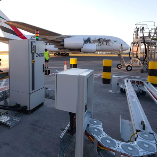
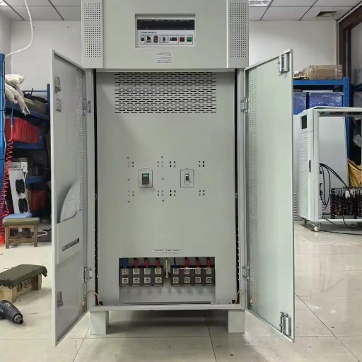
A distributed architecture places individual static converters at each gate, typically in weatherproof cabinets mounted on the jet bridge pier or in small ground-level equipment enclosures. Each converter serves only its assigned gate. A narrow-body gate gets a 90 kVA unit. A wide-body gate gets 180 kVA.
Point-of-use systems eliminate long cable runs and the associated voltage drop calculations. Each gate operates independently, so a converter failure affects only one stand. Expansion is modular: add a new gate by adding another converter without touching the central system. And installation is faster because there is no centralized electrical room to construct.
The trade-offs are higher capital cost per kVA and distributed maintenance. Instead of one large unit in a controlled environment, you have multiple smaller units exposed to outdoor conditions. Technicians must visit each gate for routine service.
For retrofits and medium-sized airports, the distributed model is often more practical. The shorter installation timeline and lower disruption to existing operations make it the default choice for facilities upgrading from diesel GPUs.
Arquitecturas Híbridas
Some airports use a hybrid approach: a centralized system for the core terminal gates with short cable runs, and point-of-use converters for remote stands or secondary concourses where cable distances would be excessive. This approach optimizes cost where centralized makes sense and flexibility where it does not.
Matriz de decisión de arquitectura
| Factor | Centralizado | Distribuido | Híbrido |
|---|---|---|---|
| Ideal para | New large hubs (12+ gates) | Retrofits, medium airports (4-10 gates) | Mixed new/remote stands |
| Tendidos de cable | Under 50 meters ideal | Bajo 15 metros | Varíable |
| Civil cost | High (electrical room, trenches) | Low (concrete pads) | Media |
| Eficiencia | 95-97% | 93-96% | 94-96% |
| Redundancia | N+1 at central level | Per-gate independence | Mixta |
| Expansión | Complejo | Sencillo y modular | Moderado |
| Mantenimiento | Centralizado | Distribuido | Mixto |
| Tiempo de instalación | 6-12 meses | 2-4 weeks per gate | 3-6 meses |
Want to explore which architecture fits your airport layout? Our engineering team can review your gate configuration and recommend the optimal approach. Contact us for a preliminary design assessment.
Fixed Installation Design Considerations
Cable Routing and Voltage Drop
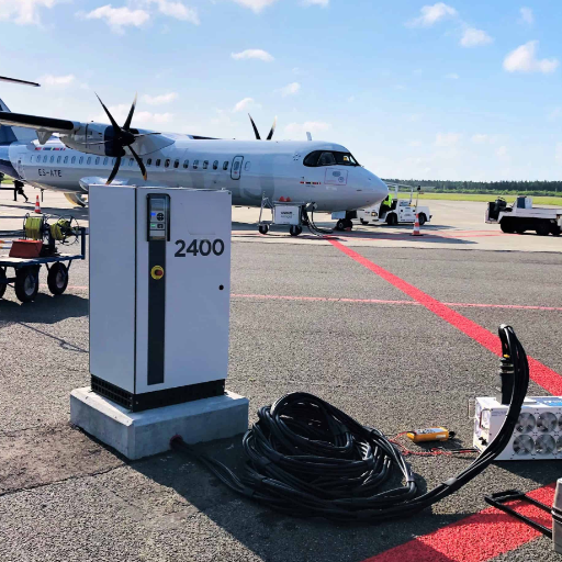
Voltage drop is the silent killer of 400Hz power quality. Aircraft electrical systems tolerate only plus or minus 3 volts on a 115V line according to ISO 6858. A voltage drop of 4 volts at the aircraft receptacle means the ground power is out of spec, even if the converter output is perfect.
At 400Hz, voltage drop is approximately 20-25% lower than at 50Hz for the same cable because of reduced inductive reactance. But the allowable drop is also much tighter. Industrial systems might tolerate 5% voltage drop. Aircraft systems demand better than 2.6%.
The voltage drop formula for three-phase AC systems is:
VD = (sqrt(3) x I x L x (R cos + X sin)) / 1000
Where VD is voltage drop in volts, I is current in amps, L is cable length in meters, R is conductor resistance in ohms per kilometer, X is reactance in ohms per kilometer, and cos is the power factor.
For a practical example, consider a 90 kVA gate drawing 225A at 400Hz through a 75-meter cable run. Using 95 mm2 copper cable with a power factor of 0.85, the voltage drop calculates to approximately 2.8 volts. That is within the plus or minus 3V limit but leaves little margin. For a 100-meter run, the same cable produces 3.7 volts of drop, which is out of spec. The solution is either to upsize the cable to 120 mm2 or to add voltage regulation at the gate end.
| Tamaño del cable (mm2) | Max Distance for <3V Drop (90 kVA) | Max Distance for <3V Drop (180 kVA) |
|---|---|---|
| 50 | diez metros. | diez metros. |
| 70 | diez metros. | diez metros. |
| 95 | diez metros. | diez metros. |
| 120 | diez metros. | diez metros. |
| 150 | diez metros. | diez metros. |
Load Balancing Across Gates
Not every gate draws its full rated power simultaneously. A Boeing 737 might be connected for 45 minutes during turnaround, but its actual power draw varies from 40 kVA during boarding to 80 kVA during engine start attempts. A parked Airbus A350 with all systems active might draw 140 kVA, but during a quick turnaround with minimal services it might only draw 90 kVA.
This is where diversity factors matter. Airport electrical designers apply a diversity factor of 0.6 to 0.7 when sizing centralized systems. This means a 6-gate airport with individual gate ratings totaling 720 kVA might only need a 450-500 kVA central converter rather than 720 kVA.
The diversity factor depends on your operation. A hub with short turnarounds and high simultaneous activity might use 0.7. A regional airport with longer dwell times and staggered schedules might use 0.6. Never size a centralized system at 100% of the sum of individual gates unless every aircraft will genuinely draw full power at the same time.
Planificación de despidos
For mission-critical gates, such as international wide-body gates or gates serving aircraft with tight schedule windows, redundancy is essential. In a centralized system, N+1 redundancy means installing one spare converter capable of handling the full load. A 500 kVA system with N+1 uses two 500 kVA converters, either in parallel or with automatic transfer switching.
In a distributed system, redundancy is inherent because each gate has its own converter. A failure at Gate 3 does not affect Gate 4. However, some airports maintain a mobile GPU as emergency backup for critical gates, providing a lower-cost redundancy option than N+1 central converters.
Point-of-Use Converter Placement
Where you place the point-of-use converter affects maintenance access, passenger experience, and installation cost. The two common locations are jet bridge pier mounting and ground-level equipment rooms.
Pier-mounted cabinets attach to the jet bridge structure at apron level. They are close to the aircraft connection point, which keeps aircraft cables short. Maintenance access requires coordinating with ground handling operations, but the location is convenient for technicians.
Ground-level equipment rooms are small concrete blockhouses positioned near the gate. They protect the converter from weather and provide a secure maintenance space. The trade-off is longer aircraft cables (15-25 meters versus 5-10 meters for pier mounting) and higher civil construction cost.
Noise is another consideration. Static converters operate below 65 dB at 1 meter, which is quiet enough for terminal areas. But the cooling fans produce a constant hum that passengers near the gate might notice. Pier-mounted units should be positioned on the apron side of the structure, away from passenger boarding areas.
Weather protection matters for outdoor installations. Cabinets need a minimum IP54 rating for dust and water spray protection. In tropical climates, sun shields and enhanced ventilation are necessary to prevent overheating. In cold climates, heaters may be needed to maintain capacitor performance at low temperatures.
Mobile and Battery-Powered eGPU Integration
Even airports with comprehensive fixed 400Hz infrastructure need mobile units for remote stands, emergency backup, and maintenance hangars. The question is how these mobile units integrate with the fixed system.
Static mobile GPUs plug into standard grid outlets (380V or 480V) and deliver 400Hz through a cable reel. For integration with a fixed airport 400Hz power supply, you need grid outlets at remote stands rated for the mobile unit’s input power. A 90 kVA mobile GPU draws approximately 140A at 380V, requiring dedicated circuits rather than standard apron receptacles.
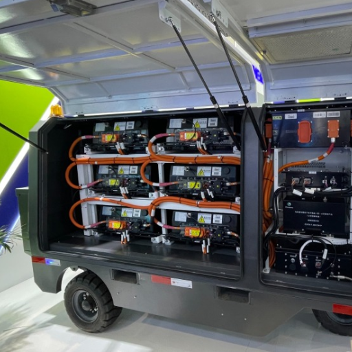
Battery-powered eGPUs are the newest category. These units store energy in lithium-ion packs and deliver 400Hz through an onboard inverter. They need no grid connection during operation, but they do need charging infrastructure. A charging station for eGPUs typically requires 30-50 kW of grid power per unit and 2-4 hours to fully charge between deployments.
Airports planning for an all-electric GSE future should install charging infrastructure alongside their fixed 400Hz systems. The same electrical distribution that feeds point-of-use converters can be tapped for eGPU charging stations with proper circuit planning.
Power Budgeting per Gate
Aircraft Type Power Requirements
The starting point for any airport 400Hz power supply design is knowing what aircraft you will serve. Ground power requirements vary by aircraft type and operational mode.
| Categoría de aeronave | Typical GPU Rating | Notas |
|---|---|---|
| Regional jets (CRJ, ERJ, ATR) | 45-60kVA | Often sufficient with 60 kVA units |
| Aviones de fuselaje estrecho (B737, A320) | 90 kVA | Most common gate requirement |
| Wide-body (B777, A350, B787) | 180 kVA | May require dual cables for some configurations |
| Super wide-body (A380, B747-8) | 270 kVA | Typically uses two 180 kVA units |
| combatientes militares | 30-60kVA | Often requires dual AC + 28VDC |
Simultaneity and Peak Demand
Aircraft do not draw their full rated GPU power continuously. A parked narrow-body with engines off and cabin services running draws approximately 50-60 kVA during normal ground operations. The peak demand of 80-90 kVA occurs only during engine start attempts or when all electrical systems are simultaneously active.
For power budgeting, use the rated GPU capacity for individual gate converter sizing, but apply diversity factors for centralized system sizing. A gate serving narrow-body aircraft needs a 90 kVA converter even if typical draw is only 60 kVA, because the converter must handle the peak without overload.
Worked Example: 4-Gate Regional Airport
Consider a regional airport with four gates: two narrow-body gates, one wide-body gate, and one flexible gate that serves either type. The airport is upgrading from diesel GPUs to a fixed airport 400Hz power supply.
Individual gate ratings: 90 + 90 + 180 + 180 = 540 kVA total.
With a diversity factor of 0.65, the simultaneous peak demand is approximately 350 kVA.
The facilities team evaluates two options. Option A is a centralized 400 kVA system in a new electrical room with cable runs averaging 60 meters to the gates. The civil cost for the electrical room and cable trenches is 180,000,andtheconvertercostis180,000,andtheconvertercostis85,000. Total capital: $265,000.
Option B is distributed point-of-use converters: two 90 kVA units and two 180 kVA units mounted on existing concrete pads at each gate. No electrical room is needed. Cable runs are under 10 meters. Converter cost is 95,000andinstallationis95,000andinstallationis35,000. Total capital: $130,000.
Option B wins on both capital cost and installation timeline. The airport chooses distributed point-of-use converters and completes the upgrade in six weeks with zero disruption to operations.
Pit Systems vs Overhead Systems
Pop-Up Pit Systems
Pop-up pit systems install 400Hz and 28VDC connection points in floor pits at each gate. When an aircraft arrives, the ground crew pulls the cable from the pit and connects it to the aircraft. When the aircraft departs, the cable retracts and the pit lid closes flush with the apron surface.
Pit systems create a clean, uncluttered apron with no trip hazards and protected cables. They look professional and are standard at major international hubs. The downsides are significant civil cost (80,000-80,000-150,000 per gate including excavation, drainage, and pit mechanisms), complex drainage requirements to prevent water accumulation, and limited feasibility for retrofit projects where apron demolition is impractical.
In tropical climates with heavy monsoon rainfall, pit drainage is a critical design consideration. Water accumulation in pits can damage cables and connectors. In freezing climates, heating elements may be needed to prevent ice formation.
Sistemas aéreos
Overhead systems deliver 400Hz power through cables suspended from the jet bridge or from overhead booms extending from the terminal building. The cables hang down to aircraft connection height and retract when not in use.
Overhead systems cost 15,000-15,000-30,000 per gate, roughly one-fifth the cost of pit systems. Installation is faster and requires minimal civil works. They are easier to retrofit into existing gates. The trade-offs are exposed cables subject to weather and UV degradation, potential aesthetic concerns, and the need for cable management systems to prevent tangling.
Criterios de selección
| Factor | Sistema de fosos | Overhead System |
|---|---|---|
| Capital cost per gate | 80,000-80,000-150,000 | 15,000-15,000-30,000 |
| Ideal para | Nueva construcción | Retrofits, budget projects |
| Apron cleanliness | Excelente | Bueno |
| Exposición al clima | Protected (if drained) | Expuesto |
| Mantenimiento | Pit mechanisms need service | Cable management needs service |
| Viabilidad de la modernización | Bajo | Alto |
| Estético | Premium | Funcional |
For the tropical airport in Southeast Asia that Shandong Electric advised last year, the choice was particularly relevant. The airport considered pop-up pits for its premium international terminal but rejected them after analyzing monsoon drainage costs. Overhead systems with UV-resistant cable jackets and automatic retraction mechanisms proved more reliable in their climate at one-third the cost.
Integration with PCA and Other GSE
Pre-Conditioned Air (PCA) Power Requirements
Pre-conditioned air units supply cooled or heated air to aircraft while parked, allowing the aircraft’s auxiliary power unit to remain off. Electric PCA units draw 30-60 kVA depending on aircraft size and climate conditions. In hot climates, a PCA serving a wide-body aircraft can draw close to 60 kVA continuously.
This power demand must be coordinated with the 400Hz GPU power in your airport’s 400Hz power supply design. A gate serving a wide-body aircraft might need 180 kVA for the GPU plus 60 kVA for PCA, totaling 240 kVA of electrical capacity. The distribution infrastructure must be sized for this combined load, even though the PCA and GPU connect through separate cables and receptacles.
Cargo Handling and Pushback Electrification
Electric cargo loaders and pushback tugs are increasingly common at modern airports. A large electric cargo loader draws 20-30 kVA. An electric pushback tug draws 15-25 kVA. While these units typically charge from dedicated apron charging stations rather than the aircraft GPU system, their power demand must be counted in the overall apron electrical budget.
The Electric GSE Transition
Major airports including Heathrow, Changi, and Los Angeles International have announced targets for net-zero ground operations by 2030-2035. This transition means replacing diesel-powered GSE with electric equivalents. The 400Hz power infrastructure you design today must accommodate not just aircraft GPU but also PCA, cargo loaders, pushback tugs, and eventually belt loaders and catering trucks.
A fully electrified wide-body gate may require 250-350 kVA of total electrical capacity:
- GPU: 180 kVA
- PCA: 60 kVA
- Electric pushback: 25 kVA
- Electric cargo loader: 30 kVA
- Margin and future growth: 20-30 kVA
When sizing your airport 400Hz power supply, plan for the full electrified gate, not just the aircraft GPU. It is far cheaper to oversize cables and distribution today than to retrofit them in five years.
Cost Comparison by Architecture Type
Desglose del costo de capital
| Componente de costo | Centralized (6 gates) | Distributed (6 gates) | Hybrid (6 gates) |
|---|---|---|---|
| Converter hardware | $85,000 (500 kVA) | $105,000 (mixed units) | $95,000 |
| Electrical room / civil | $180,000 | $25,000 (pads only) | $120,000 |
| Cable and ducting | $75,000 | $20,000 | $55,000 |
| Aparatos de distribución | $35,000 | $8,000 | $25,000 |
| Instalación y puesta en servicio | $45,000 | $30,000 | $40,000 |
| Capital total | $420,000 | $188,000 | $335,000 |
| Cost per gate | $70,000 | $31,000 | $56,000 |
Comparación de costos operativos
Centralized systems have lower maintenance costs per gate because all equipment is in one location. Annual maintenance for a 500 kVA centralized system runs approximately 4,000-4,000-6,000. Distributed systems require visiting each gate, pushing annual maintenance to 8,000-8,000-12,000 for six gates.
Energy efficiency slightly favors centralized systems. A 500 kVA converter at 96% efficiency loses 20 kW as heat. Six 90 kVA converters at 94% efficiency lose a combined 32 kW as heat. At 2,000 operating hours per year and 0.12perkWh,thecentralizedsystemsavesapproximately0.12perkWh,thECEntralizedsistemsavesapproximately2,900 annually in energy costs.
Costo total de propiedad en 10 años
| Arquitectura | Capital | Energía a 10 años | Mantenimiento de 10 años | Costo total de propiedad (TCO) de 10 años | TCO per Gate |
|---|---|---|---|---|---|
| Centralizado | $420,000 | $57,600 | $50,000 | $527,600 | $87,900 |
| Distribuido | $188,000 | $86,400 | $100,000 | $374,400 | $62,400 |
| Híbrido | $335,000 | $72,000 | $75,000 | $482,000 | $80,300 |
The distributed system wins on 10-year TCO for this 6-gate example, primarily due to significantly lower capital cost. The centralized system only becomes competitive at larger scales (12+ gates) where the capital cost per gate drops and the energy savings accumulate.
Preguntas Frecuentes
How much does an airport 400Hz power supply system cost?
Capital costs range from 30,000-30,000-70,000 per gate depending on architecture. Distributed point-of-use systems average 30,000-30,000-40,000 per gate. Centralized systems average 50,000-50,000-70,000 per gate for new construction with electrical rooms and cable trenches. These figures include converter hardware, cables, civil works, and installation.
Can I retrofit 400Hz power into an existing airport?
Yes, and distributed point-of-use systems are the most practical approach for retrofits. Individual converters can be installed at each gate on existing concrete pads with minimal civil works. A typical 4-gate retrofit can be completed in 6-8 weeks without disrupting normal operations. Centralized systems are rarely feasible for retrofits because they require dedicated electrical room space and extensive cable trenching.
How far can 400Hz power be transmitted before voltage drop becomes a problem?
With properly sized cables, 400Hz power can be transmitted up to 100 meters while maintaining ISO 6858 voltage tolerance (plus or minus 3V). For a 90 kVA gate, 95 mm2 cable supports runs up to 68 meters. For 180 kVA, the same cable supports runs up to 34 meters. Beyond these distances, cable size must increase or voltage regulation must be added at the gate.
Should I choose centralized or distributed architecture?
Choose centralized for new large-hub construction (12+ gates) with short cable runs and central electrical room space. Choose distributed for retrofits, medium airports (4-10 gates), and facilities needing modular expansion. Choose hybrid when you have a core terminal with short cable runs plus remote stands or secondary concourses.
What electrical room requirements does a centralized system need?
A centralized 400Hz system needs a climate-controlled electrical room with adequate ventilation for converter heat dissipation, clearance for maintenance access on all sides of equipment, fire suppression systems, and space for future expansion. Room size scales with converter capacity: approximately 15-20 square meters for a 500 kVA system, 25-35 square meters for 1,000 kVA.
How do I size cables for a 400Hz system?
Use the three-phase voltage drop formula with 400Hz-specific reactance values. Account for the tight aircraft voltage tolerance (plus or minus 3V). Size cables so that voltage drop at the aircraft receptacle stays within spec under maximum load conditions. Include a safety margin of at least 20% below the limit to account for temperature variations and cable aging.
Can 400Hz power infrastructure support electric GSE beyond aircraft GPU?
Yes, and it should be designed with this in mind. Electric PCA, cargo loaders, and pushback tugs all draw power from the same apron electrical infrastructure. A fully electrified wide-body gate may need 250-350 kVA total. Size your distribution cables and transformers for the full electrified load, not just the GPU portion.
What is the typical lifespan of an airport 400Hz power installation?
Static converter hardware lasts 15-20 years with proper maintenance. Cables and electrical distribution infrastructure last 25-30 years. Pit systems last 20-25 years depending on drainage and maintenance. Point-of-use converter cabinets may need refurbishment or replacement after 15 years, but the underlying cables and distribution typically outlast the converters.
Conclusión
Diseñando un airport 400Hz power supply system starts with one decision that shapes everything else: centralized or distributed architecture. That choice determines your civil costs, cable lengths, redundancy strategy, and expansion flexibility. Get it right and you have a scalable, efficient system that serves your airport for decades. Get it wrong and you face voltage drop issues, budget overruns, and limited growth capacity.
The key principles are straightforward. Size your system for the full electrified gate, not just the aircraft GPU. Apply diversity factors intelligently for centralized systems. Size cables for voltage drop with a safety margin. Plan for the electric GSE transition that is already underway at major airports. And choose pit or overhead systems based on your climate, budget, and new-build versus retrofit status.
Whether you are designing a new concourse at a major hub or upgrading a regional airport from diesel GPUs, the infrastructure decisions you make today will determine your operational costs and reliability for the next 20 years. Shandong Electric designs and manufactures both centralized and distributed airport 400Hz power supply systems, with custom engineering support for cable sizing, gate budgeting, and full system integration.
