
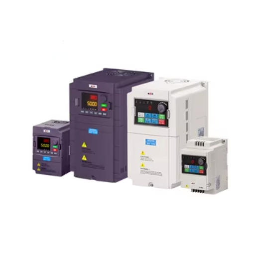
When the model is expanded to involve industries and applications that have cross-border operations, finding common ground between different electrical standards which are frequency dependent remains a major obstacle. Differences that often emerge in the form of the 60 hertz and 50 hertz transmission lines by the equipment cause operational inefficiencies, usability challenges, and the compatibility of electrical equipment. One is the three-phase frequency converter; it has been designed to address this issue without you even noticing it. In this post, we elaborate on the main aspects of such a 60Hz to 50Hz frequency converter, user the specific working of the device as an example to explain how electrical power can be seamlessly integrated within different systems.
Brief Introduction of Frequency Converters
A frequency converter involves the change of an input electrical frequency to correspond to a specific output, thanks to which power supplies and equipment mesh perfectly. There are three main steps in carrying out the activity: rectification, inversion, and modulation. The first task is to change the supplied AC power to DC power using rectification. After that, the obtained DC power is changed to the involved frequency in AC using an inverter. And finally, the output is perfected using modulation techniques for specific benefit, say to maintain a voltage by using a voltage level. This entire method is used when one operation at least that is phased for the power utilities, is being directly replaced by something designed to work well when powered at something different like from a 60Hz to a 50Hz source.
What is a Frequency Converter?
Another transformed electronic apparatus is the frequency changer, which has been designed to change an alternating current frequency to match a distinct equipment or system requirement in a given situation. This is accomplished by using a sophisticated power electronics and control system to transform input power into the required output frequency and voltage. A standard practice of using a frequency converter includes the following three stages of operation in brief. Firstly, the input AC power is converted to DC using rectifiers (diode- or thyristor-based). Secondly, the DC is inverted in order to generate another AC waveform of a new frequency. Subsequently, the output wave quality can also be improved by the use of sophisticated modulation techniques, i.e., pulse-width modulation (PWM), integrated into the system.
There are many varieties of frequency converters in the market and their capability and application differ. The most comprehensive of all is the use of them to allow the usage of displays in other areas; to adjust the speed of motors; or with precision operation necessary without damaging the equipment. The use of insulated-gate bipolar transistors (IGBTs) with the latest technologies and other advancements in the modern era have presented better operational capabilities and have become a competitive technology. Especially with the manufacturing sector and the marine environment, as well as all segments of renewable energy source integration.
Types of Frequency Converters
| Type | Key Features | Applications | Efficiency | Cost |
|---|---|---|---|---|
| Rotary Frequency Converters | Mechanical-to-electrical conversion | Industrial and marine systems | Moderate | Medium |
| Static Frequency Converters | Fully electronic design | Aerospace and renewable energy | High | High |
| Motor-Generator Frequency Converters | Combined motor and generator use | Versatile industrial settings | Moderate to High | Medium to High |
| Matrix Converters | Direct AC-AC conversion | Compact and energy-efficient use | Very High | High |
| High-Frequency Converters | For high frequency requirements | Telecommunications, radar systems | High | Expensive |
Applications of Frequency Converters
- Aerospace Industry
Many varieties of frequency converters are found in the aerospace industry that are used for maintenance of aircraft power systems when it is necessary to synchronize various equipments with different input and output frequencies. When it is necessary to work on processing accurate signals in ultra high frequency range, high-frequency converters are generally used for advanced radar systems. - Renewable Energy
Frequency converters are used to incorporate generated electrical power from wind mills and solar plants with the grid utilizing energy storage. Keeping the grid system frequency in control is pretty important to avoid loss in the power distribution and reducing the plant’s efficiency. - Telecommunications
High-frequency converters contribute greatly to telecommunication in reshaping signals, changing the frequency between equipments as the devices enhance communication on different bands with the help of these converters. Using these converters provides a way to send information over a great distance. - Industrial Automation
There are many instances with industrial machinery where motor-generator frequency converters are employed as machines may need to be adjusted to different working speeds. It also simplifies the production process by allowing variable-speed motors to work at their maximum efficiency in different manufacturing operations. - Marine Equipment
Marine vehicles are commonly installed with matrix power converters for the purpose of adapting to the power frequency changes of the electrical system inside either the vessel or any other stationary outside power system. This advance helps in ensuring compatibility with available shore power as well as compatibility with the EU electrical systems. - Consumer Electronics
Consumer devices have frequency converters to optimize performance by changing the voltage or frequency output. Especially in the case of matrix converters, they incorporate this feature with small packaging which does not need a lot of space for installation to maintain power and energy reduction or saving.
Three-Phase Frequency Converters
Three-phase frequency converters play important functions in the areas of industry, business or economy, and energy. These have been specifically developed to cater for greater power transfer, therefore, suitable for electrically operated heavy machinery, HVAC, as well as renewable energy gadgets (e.g., wind turbines). The biggest selling point of the converters is the fact that they possess high transformation efficiency that converts electrical power of one frequency to another frequency perfectly hence operation under fluctuating conditions of any electrical specifications. In addition, the systems offer energy conservation and prolonged life of high power equipments in the sense that they lower electrical disturbances which ruin the equipments.
Overview of Three-Phase Systems
Characteristics of three-phase systems in relation to modern electrical engineering and energy distribution are various, including the uniqueness and advantage of steady and balanced power delivery. In these systems, there are three waves that are 120 degrees apart and are continuously transferring electric power. This also explains why the modulation of the power is reduced in this kind of system, unlike in single phase systems which vary to a greater extent shall be found in the industrial frequency electrical systems and such systems as high powered generation.
A major differentiating factor among three-phase systems is their capability in providing a larger power output from a lesser conductor length owing to the three-phased structure of such systems. As an example, three-phase power transfer involves 25% lower electrode lengths in the same power output, thus reducing the cost and weight of materials for large-scale configurations. It is also worth mentioning that these systems accommodate the usage of the three-φ motors that are smaller, more effective, and wear less than the single-phase induction motors, which makes them must-have machines for any heavy and industrial equipment.
The versatility of three-phase systems is enhanced by the fact that they can support various configurations like wye (star) and delta connections which are preferred based on the voltage and current they need to carry. The development of technology and reliable grid systems along with the three-phase systems have over the years brought about a lot of enhancements making it possible to incorporate the systems with the contemporary renewable energy systems, flexible networks using smart grids and hybrid wind grid systems.
Benefits of Using Three-Phase Frequency Converters
- Enhanced Energy Efficiency
Three-phase frequency converters make it possible to save energy by regulating the speed of the motor to adjust it to a set load. It helps to lower operational costs thereby enabling energy savings in the range of 30-60% - Improved Motor Performance
Nevertheless, these frequency converters lessen vibration and overheating while increasing the frequency of the motor output. Such proper motor control operations in a system design limit vibration and heat-related stress depending on the application, benefitting the lifespan of the engines and the maintenance scope, which means less downtime and repair cost. - Precise Speed and Torque Control
Frequency converters make it possible to regulate motor’s speed and torque hence allowing the system to operate in processes that entail changes in the motor output, for example conveyors, pumps and industrial machine tools among others. - Reduced Electrical Losses
In comparison to the single phase system, three phase converters have less electrical heat loss as they contain a more balanced power load thus can enable a more fair power sharing among the elements, hence increase the system and operation efficiency. - Compatibility with Renewable Energy Integration
Most green energy sources, such as wind or solar for instance, are fitted with frequency converters. And their basic function is to ensure that energy exchange they hold is done at the regularity and absence of deformation. - Support for Smart Grid Applications
Frequency converters of this kind possess unique structure and provide smart energy management system interface. This enables grid to be more flexible and to make real-time response, control, and overall system improvement.
Comparison with Single-Phase Frequency Converters
| Parameter | Three-Phase Frequency Converters | Single-Phase Frequency Converters |
|---|---|---|
| Power Output | Higher, suitable for industrial applications | Lower, ideal for small-scale use |
| Efficiency | Greater energy efficiency | Lower energy efficiency |
| Voltage Stability | Superior voltage stability | Prone to voltage fluctuations |
| System Complexity | Requires advanced systems integration | Simpler system design |
| Load Balancing | Automatic load balancing capability | Limited or no load balancing |
| Applications | Heavy machinery and large-scale systems | Household appliances and light-duty equipment |
| Initial Cost | Higher initial cost | Lower initial cost |
| Maintenance | Requires specialized maintenance | Easier and less costly maintenance |
| Grid Compatibility | Fully compatible with smart grid technologies | Limited smart grid compatibility |
| Energy Integration | Supports renewable energy sources | Less compatible with renewable integration |
60Hz to 50Hz Frequency Conversion
The transmission of 60Hz and 50Hz is essential when devices that are made for one frequency need to be used within the network of systems of another frequency. Generally, the procedure is with frequency converters, which are generic structures designed to the preserve the original frequency within the range as required. The efficiency of the course is highly reflected in the consumption and the quality of power supply that is usually provided, which will show if it is difficult. Finally, the application of voltage that is not supported can cause even more vicious damage to equipment that was not even experiencing distress due to the different frequencies and this would require a second report to be made.
Why Convert from 60Hz to 50Hz?
The need to go from 60Hz to 50Hz is one reason societies varying in terms of electrical frequency objectives necessitate a conversion. It is not new to know that there are a lot of countries using a 50Hz system, while some such as the United States have a 60Hz system. When international businesses come into play, ensuring that devices do not only comply with electrics but can be used anywhere within these countries is very important as it may cost more time and money in corrections, maintenance or replacing equipment that stands and does not work. The conversion is also essential in cases where industrial equipment is being imported or exported, as machines built under 60Hz supply may be and are likely to be rendered inadequate or hazardous in 50Hz areas of installation without adjustment.
Equally important is apprehending the synchronization of electrical installations with all the additional equipment, supplied by different frequency standards. Absence of this synchronization can result in operational discrepancies, power loss or even increase in the wear and tear on the equipment. Not only that, but some electrical systems, such as motors and transformers, are so closely related to the frequency that even slightly different supply frequencies will have negative effects. It is not recommended that such systems are run at a different frequency as that will naturally cause unwanted changes such as reduction in driving power, overheating or modification of speed-torque trades. Creating frequency changers meets international standards and enables improved performance and longer service life for machine masses on site.
Technical Challenges in 60Hz to 50Hz Conversion
There are a few technical problems when adapting systems to 50 Hz frequency from 60 Hz. Every electrical-based issue surrounding the reactance in the components varies with frequency. When it is reduced from 60 Hz to 50 Hz, the inductive reactance of motor transformers and other inductive equipments will also increase. This increase came along with high inrush currents and increased losses resulting from the increased resistive loads.
It turns out the next pressing issue is regarding speed of the flow as well. The speed of rotation of an ac motor is determined by the formula 120 × Frequency / Number of Poles. That is, a reduction in the frequency of the supply voltage causes the motor to slowdown proportionately, which affects the power output of industrial products which expect to work like that. This can prompt changes in the mechanism or/and use of some advanced means for frequency control to preserve the ability of the machinery to function at the needed speed.
Moreover, 50 Hz frequency transformers can result in the core saturation of 60 Hz transformers as they are designed to operate efficiently at that frequency. Reduced frequency also entails reducing the volts per hertz ratio which may induce magnetizing current and core loss. One way to overcome this is by oversizing the transformer or changing the material for the core.
Static Frequency Converters for 60Hz to 50Hz
Static Frequency Converters (SFCs) are advanced devices that provide excellent and versatile solution for power conversion from 50Hz to 60Hz and back. Their operating principle is based on semiconductors such as Insulated Gate Bipolar Transistors (IGBTs) which enable control of the entire frequency conversion spectrum with high accuracy and efficiency. An important benefit of Static Frequency Converters is that they can accommodate equipment operation when designs are based on other frequency standards. Hence, these converters are vital in modern industries and transportation systems which are interconnected worldwide.
In industrial manufacturing, shipping and aerospace among other sectors, equippment is designed such that it can be used under any available power supply conditions. For example, in import and export businesses one many need and use a frequency converter in order to enable the use of equipment that runs in America, which is served by a 60Hz power supply, in a European country that has 50Hz power supply. In addition, the use of static frequency converters is very common in aviation ground power units (GPUs), which are used to supply power to the airplane while it is on the ground, thus enabling uninterrupted operations.
The introduced recent breakthroughs held in downsizing and enhancing its performance with attributes such as high density, high performance, scalability, minimizing higher harmonics, as well as increasing many that were light, many to be much heavier, and or contained within the smallest shoe box designs. These very factors, coupled with their good endurance and dissipative heat-loss control potential during operation, provided improved robust designs, making systems more reliable and contributing to enhanced efficiency, thereby lengthening their lives and minimizing maintenance costs, thereby reinforcing broader utilization of the device in frequency conversion.
Specifications and Ratings
It is generally true that frequency converters in technical terms are described based on the range of the input source voltage and the frequency of the output frequency, the range of power they can sustain and the proportion of this power which is converted into useful power for the device. The input voltages ready for these types of devices are typically ranging from 100V up to 690V AC, and the wide output frequency comprising of 0.1 Hz up to and often exceeding 400 Hz so as to suit the wide ranging operational needs. The power supply units of converters vary with the required voltage level; some are as small as a few kilowatts and are portable, while others are large enough to exceed several megawatts and have broad industrial applications.
Understanding KVA Ratings
Kilovolt-amperes (kVA) is a unit of measure used throughout electrical systems, indicating the net power delivered by transformers, motors, or uninterruptible power supplies (UPS). Active work performed in kilowatts (KW) is joined by reactive power in kVA, so the total of the two can be used to size equipment to match load requirements. The kVA to kW ratio is affected by the power factor. This is the ratio of real power to reading power, typically measured as a decimal or percentage of the efficiency with which electric power is applied to perform work.
For example, a power factor of 0.8 would theoretically guarantee ideal performance of 100KVA device at 80 KW. In his day, many electrical appliances are already equipped with power factor correction for efficient utilization of power and hence reduced use of flooding the system with unnecessary reactive power. Engineers must carefully size KVA capacity taking into consideration duty, pattern characteristic of load, anticipated overloading and even sudden enchacies or inrush currents which the system shall accommodate. Capacity in KVA should be right in such a way that it cannot cause overheating and cause performance problems, hence it is important so that the system remains effective and operational for longer.
Common Voltage Ratings: 380V and 480V
Voltage ratings of 380V and 480V are common in many industrial and commercial operations. A rate of 380V is used in most places in Europe and Asia, and provides the delivery of current in three phases at 50 Hz. It can be used for distribution purposes able to cover distances that would be too great without a decrease in efficiency and without energy dissipation. Wasting power while the energy flowing in the wires makes it an ideal system for most environments.
In the United States and elsewhere in North America, 480V configurations are generally more common and run at a 60Hz frequency. This particular voltage cycle is vital for many heavy industrial functions such as, but not limited to, involving both motor drive power, pump working, heavy machine movement power where more power is needed but less current consumption is required. Hence lower current requirements result in reduction of the size of conductors used meaning that the costs of installation and operation decreases.
Voltage configurations are one of the most important components of the global electrical infrastructure hence their selection is often determined by the proximity of equipment and the set operational needs, Moreover, engineers consider crest factor, voltage drop and equipment tolerance while designing systems using these voltage grades to ensure safety, efficiency, and the adherence to the Regional Regulations.
Choosing the Right KVA for Your Application
The choice of KVA (kilovolt-ampere) that may suit a specific purpose is really not an easy walk through, because it involves deep knowledge of the energy requirement of the system if it is to work at all and the purpose of the electricity. The key aspects for evaluation are gross power input desired, the character of load whether inductive, resistive or inductive, and any abnormally high loads such as surge, that might occur during operations.
There is also the factor of power factor that has to be accounted for since the power that is noted on the KVA scale is also different from that recorded on the KW scale. Often in industrial applications with large quantities of inductive loads mainly motors and transformers, the lagging power factor is lower, which makes it necessary to use KVAs that are higher in order to avoid tripping or brownouts of the appliances. Any future expansions on the load or power factor should also consider the room for growth to effectively resolve issues with overloading the current system.
When making calculations, it is important to take into account the drop in voltage and the efficiency of distribution system so that the system can work properly even when the wires are too long or the load is constantly changing. Synthesis barriers are fundamental to preventing the dimensions of the equipment from being inadequate, leading to too much ad hoc maintenance, or too huge resulting in increased spending and service performance degradation.
Installation and Operation
Proper installation should not be neglected as regards to all manufacturer instructions and norms that must be followed for safety and functionality reasons. Before components can be installed, each and every part has to be checked for any defects, and all connections must be tightened without failing to ensure the parts are accurately positioned as per the approved plan. In order to ensure the workability of the systems in question, it is necessary to carefully monitor performance at all times and in case of any deviations to either rectify these deviations. For the best results, consider performing ongoing system sie bath audits, include preventative maintenance and cleaning of key components to make the system last longer and not wear out quickly.
Installation for Three-Phase Frequency Converters
As concerns the installation work of the three-phase frequency converter it should be done in a respective way without silence on any of its attributes as it is read in the concept, by to sum up, and rules. Before starting installation works, it is necessary to establish that the supply voltage is appropriate to the rated input voltage of the frequency converter. Employ shielded cables that the manufacturer have provided with the equipment and well-ground the system to reduce electromagnetic interference (EMI), as a general precaution and also in accordance with electrical codes hence protecting the installation area and the persons using the equipment.
The installation location should be suitable, clean from dust, excessive heat or humidity to prevent overheating and pollution of the unit. Leave hooting within the minimum technical clearance around the converter in order to consent to the aircraft of the whatabout proper air flow. When wiring the will measure ensure the appropriate flow of the phase sequence, avoiding phase shift, motor hazard, and consequently poor working conditions.
Moreover, the operating settings of the rotary converter – motor parameters – are to be set via the manufacturer-supplied software or interface. These include motor type, frequency range, as well as acceleration/deceleration rates in relation to the application requirements. Above all, testing the system at low load is critical to ensure no functional issues after the shift to full load. Such a system ensures that all safety requirements are met and improves the performance of an operator.
Operational Considerations
Energy efficient operation is one of the most crucial operational factors to consider in modern converters since it leads to reduced costs of operation as well as improved service lifetime. Power efficient inverters are integrated with advancements in the semiconductor technology being used in the fabrication of high reliability materials such as the power devices and structuring the converters. Furthermore, the thermal performance has an important role in the efficiency and life cycle of the equipment.
Dusting with use of heat sinks and strong air ventilation in the fan so as to preclude the components from reaching and operating at over temperature enhances the chances of the host systems in general even when there is no room for error. There is also an ongoing process of evaluating the thermal capacity and the temperature rise through a cycle as too much heating may destroy the system’s function and even damage it. Consideration of these issues and includes the contours of comfort zone enables the control and operation of the converter from exceeding margins and also maximizes the efficient use of energy throughout its lifetime.
Reference Sources
Frequently Asked Questions (FAQs)
Can I use a frequency converter to run a 60Hz motor on a 50Hz supply?
Of course, a motor can be operated on a system with 50 Hz power supply and at a frequency of 60 Hz. This is possible if the right voltage is available or if the inverter has good dynamics to meet the required value of magnetic flux of the motor by adjusting the current. The management of overcurrents is done by voltage control, otherwise the transformers need to be low-frequency rated within the internal voltage levels. There are also voltage control techniques that develop the skill of slowing a motor down if the base line operational speed is not necessary together with its associated generated torque. Utilising a phase converter or even a synchronous converter can be ineffective because such devices do not provide as much trial as a purpose-drved inverter does.
How do I size a 60Hz to 50Hz frequency converter for my 3-phase motor?
When choosing a variable frequency drive, it is advised to select a VFD with power rating, which is greater than 15% and less than 25% of the rated power of the motor to cater for all starting and overload conditions and that the voltage and current ratings of the VFD fits that of the motor. Analyse whether the software can handle sizing of drives with regard to peak torque for load torque and duty as well as soft starting for the motor and if it has a braking system. It is also worth noting whether substantial distances will be connected by the network or if the load is affected by harmonics; if so, employ the capabilities of RVSS and use the drive-induced harmonics mitigation. This has to be done using the other equipment.
Will a frequency converter change voltage as well as frequency when converting 60Hz to 50Hz?
In the modern day, it is commonplace for the frequency converters to be able to control both frequency and output voltage with the help of V/Hz or vector control for maintenance of appropriate motor flux and torque properties shift from 60 Hz to 50 Hz and vice versa. In the case of simpler converters, it is possible that only the desired frequency is changed even though the voltage can be adjusted by another transformer. Moreover, very often, power factor correction and an isolation transformer are built into the inverter to assist stabilization of the output power to make it clean and healthy. It is important to consider the inverter’s voltage regulation and the allowable voltage variation at the connection, given the motor’s voltage class.
Can a frequency converter provide both 60Hz and 50Hz outputs for different machinery?
Yes, many modern frequency converters and VFDs are flexible such that they generate and then give out several frequencies by default and can produce, say 50Hz to operate one load or 60Hz for another load making it ideal for operating mixed equipment. Other modules come with multiple channel output or many VFDs in a single cabinet for a variety of machines. Use-ready the converter must assist for each load the required switching, synchronization control, and protection. If circumstances require, employ synchronized or even redundant converters to supplement the system under consideration, especially for mission-critical applications, when a down period should be minimized, and no motor performance should be affected.
