
Rotary frequency converters are an important aspect that helps connect electrical equipment and machines that need power at non-reprocessing frequencies. This is effectively the fundamental working principle of such a device, as it changes the current from one phase to another at a certain frequency, and is utilized in a number of different sectors like aviation, manufacturing and maritime purposes. Furthermore, how is it possible that such devices function that way, and how is it possible to operate the modern devices without these devices? In this article, the fundamental principles and applications of rotary frequency changers will be analyzed. This guide will also provide an in-depth analysis of the various aspects of power systems, including design, performance, and importance, irrespective of the individual being an engineer, a technician, or experimentally oriented in power systems.
Core Definitions of Rotary Frequency Converters
A rotary-converter device is an electrical power tool that has the capacity to alter frequency of electric current. It works by taking electric power from an input motor and passing it through a generator. In this case, the power runs off at a specific frequency in the generator, allowing the motor to function at a source frequency and the generator to produce power at an output frequency at the same time. This is particularly crucial where some equipment runs at a different frequency to that of the mains as it eases the conversion of 60 Hertz power supply to 50 Hertz and the opposite. The equipment is set up in a manner that the frequency changes so that power is supplied when necessary, while still meeting security measures that do not require unnecessary alterations. Industries like aviation, manufacturing and maritime applications are some of which prefer rotary frequency converters, as they ensure that the power and the equipment are useful together.
What is a Rotary Frequency Converter?
The rotary frequency converters are machines that do wonders in converting electrical energy from one frequency to another. This is because the devices come in handy in connecting at variations in systems and equipment that operate on different frequency standards. Also, for the persistent use of the rotary frequency converter, it effectively uses the motor generator where the motor takes the input frequency, and the generator takes it to the required output frequency. It has been proven in other studies that rotary systems operate efficiently especially when making frequency transitions without significant introductions of electrical noise or instability.
Located in factories and other industrial areas needing strict frequency control and management, the rotary frequency changers are known for their sturdy build as well as ability to work on high power loads for extended lengths of time. Such systems have proven to be very helpful when it comes to precision power conversion and parallel applications with total accuracy in a number of areas, such as aviation support on the ground and even in naval shipbuilding.
Importance of Frequency Conversion
The role of frequency conversion in systems powered by alternating electricity is immense. The main reason why adding transformers seems necessary is because of the frequency diversity, namely discrepancy between regional and global standards. For example, for a machine designed for 50Hz operation and used in a country with 60Hz operation, the operation is problematic. Such a difference, operational or utilization, may lead to operational wastage, equipment damage, or non-optimal operation.
Certain economic sectors, say mechanical engineering and aerospace, cannot do without frequency converters in order to preserve serviceability and longevity of highly sensitive tools and equipment. Currently, these devices are made so that they solve board’s distortion and unbalance problems which would compromise the working of the equipment. These systems are also used in digital techniques and it increases energy consumption because they are used in renewable energy systems, grid interconnection, marine propulsion and embedded drilling and excavation systems.
It is often argued that such systems are necessary for the switch to more environment -freindly sources of energy. These systems or converters offer power flow compatibility which is sensitive to the system or its geographical structure thereby giving rise to the development of a worldwide energy network. As such, the utility, dependability, and versatility of these converters will keep them both relevant in the traditional industry set ups and other fast and modern systems.
Components of Rotary Frequency Converter
| Component | Description | Key Parameters |
|---|---|---|
| Electric Motor | Converts electrical energy to mechanical energy. | Speed, Torque, Efficiency |
| Alternator/Generator | Converts mechanical energy back to electrical energy. | Voltage, Frequency, Capacity |
| Flywheel | Stabilizes fluctuations in rotational energy. | Weight, Material, RPM |
| Control Panel | Monitors and regulates converter operations. | User Interface, Sensors |
| Bearings | Reduce friction in rotating parts. | Friction Coefficient, Durability |
| Cooling System | Maintains optimal operating temperature. | Cooling Type, Capacity |
| Input Transformer | Adapts input voltage and current levels. | Voltage, Current, Power Rating |
| Output Transformer | Modifies output voltage and current levels. | Voltage, Current, Efficiency |
| Frame/Enclosure | Provides structural support and protection. | Material, Size, Durability |
The Physics of Rotary Frequency Conversion
Rotary transformation generally operates on the underlying idea of electromagnetic induction. The kind of apparatus it comprises of is characterized by the use of a chief rotating entity that is usually an electric motor- alternator configuration meant to augment power between two given frequencies. While the motor is rotated, it generates a sympathetic electrical field in the alternator. This electronic field, upon receiving the components, interacts with the alternator winding to, in return, generate the supplied voltage and current at the required frequency.
The frequency of the pulsed electrical supply drives the motor, and it is ultimately the speed and the design of the alternator that dictates the magnitude of the output frequency. This behavior is well-suited for use if a constant conversion ratio is required, like aerospace, industrial plants, or ships. The conversion accuracy is affected by the virtues of the components as well as alignment and load factors.
Mechanical-to-Electrical Energy Transfer
Within electromechanical devices, the transformation of kinetic into electrical energy is performed. This regenerates electrical energy and directs it towards generators. Electromagnetic induction is the main idea of these systems as Faraday”s Law explains. According to this concept, when a magnetic field is enclosed in a quest of motion, a soft wire formed like a coil is forced to move. Consequently, an electromotive force, being none other than an emf, is induced here calling for there to be a current of electricity present. The degree of this effect is controlled by the linear speed of the conductive element through the changing magnetic field and relative distance with compression to the magnetic field as well as the magnetic field intensity and inductance response of the coil.
Cutting-edge technologies often exploit unconventional materials in order to enhance performance, such as heavy-duty electric motors and sarbatage windings. These systems also call on computational aids to achieve perfection in the construction adjustment of the rotor and stator sections in order to minimize losses and maximize conversions. These ensure that the transformation energy effects are performed with greater energy transformation and adaptation to the energy of actuators like renewable energy systems, vehicles, and manufacturing, among others. Industries using this technology supplies high-precision devices and systems with high-efficient energy conversion.
Relationship Between Rotational Speed and Frequency Output
In the case of electromechanical force and its relationship to speed, common sense prevails. The power generators and electric motors are electrical and mechanical machines. In such cases, the frequency output (f) is proportional to the speed of rotation (N) of the perpetual magnet and the number of poles (P) on that machine. This relationship is expressed by the following formula:
f = (N × P) / 120
Where:
- f is the frequency in hertz (Hz),
- N is the rotational speed in revolutions per minute (RPM),
- P is the number of poles.
The formula described shows the rate of output nature of the system’s operation as a function of the mechanical speed and the range of poles when in total rated condition. For equipment that runs synchronously, where hysterisis in the frequency response characteristic caused between the external grid source and the synchronous generator is to be balanced at the system’s rated frequency typically at 50Hz or 60hz, sophisticated speed control is necessary.
What is more, reserves have been established due to the development/growth of control measures such as the use of variable frequency drives (VFDs) and high-performance digital control systems, and the more advanced regulation of speed and other parameters. The introduction of these devices makes it possible to operate under various levels of loading while ensuring the stable output frequency always falls within the acceptable limits, which is crucial in power production, automation and green energy sectors.
Understanding Phase Relationships in Frequency Conversion
In electrical power system, the relationship between voltage and current is crucial. As it is important for the energy exchange, power stability (from different generators) and different networks synchronization to be maintained, the frequency and power conversions are a very critical component of power system engineering. Phase shift can be thought of as the relative position of the cosine graphs of current im measured in degrees or simply other sine and cosines that are out of phase. This control is hugely important because, in the absence of it, smooth energy transfer will not be possible, and the system cannot function properly, especially in the case of grid-connected renewable energy or ultra-hyper-precision manufacturing.
Current frequency changers are even equipped with superior software and sophisticated techniques empowered with fast speed circuitry for period control. An instance is when interconnected alternators are used with wind energy or solar energy systems. It can be said without fear of contradiction that phase matching in this case makes certain that the output voltage waveforms are exactly in alignment with those of the grid leading to minimum losses and distortion of power. In addition, the worldly practice of utilizing phase – locked loops (PLL) is convenient. Inside this converter, phase–lock loops permit, within the requisite tolerance, even the phase disturbances under changing load and transient conditions.
Component Deep-Dive into Rotary Frequency Converters
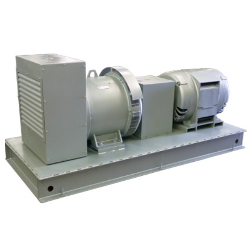
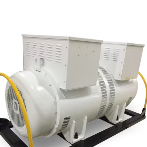
- Rotary Motor-Generator Set
This motor-generator set is the central piece of the equipment in a frequency converter circuit. The spindle, or the motor, is made to rotate and as it does a generator is turned. This factor is very crucial when applying frequency conversion by limiting or shifting the incoming power to output frequency values.
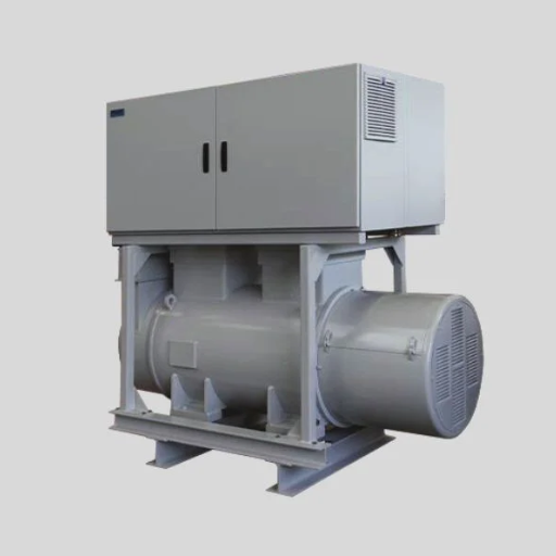
- Control System
State-of-the-art control circuits also take it upon themselves to control the speed and reactive power of the generator to increase the accuracy of the conversion. Such control architectures can include switches, relays, and programmable automation controllers or microprocessors for hands-on operation of the system.
- Bearings and Couplings
The mechanical parts especially the bearings, couplings, are very important for the transmission of power, as they are used to transmit the energy between the motor and the generator without much losses. High-quality bearings extend the ability to work effectively and reduce the possibility of undue wear.
- Cooling Mechanism
Once the equipment is in operation, the motor-generator set and all associated components must not overheat. This is why it is very important that the components are designed in such a way that even prolonged use does not wear them out and the performance under load is not affected significantly.
- Power Input and Distribution Interfaces
These are the subsystems, which are involved in the link between the voltage power supply system, the converter and the load. They usually consist of filters and transformers to overcome harmonics and to protect the equipment from negative phenomena associated with electric interference.
Induction and Synchronous Drive Motors
Induction motors or asynchronous motors depend on electromagnetic induction producing working electric currents in either the rotor or the stator, as the case may be. They are very physically sturdy, and have an ability to operate for long periods while being almost maintenance free since they do not have brushes or commutators. These motors are widely used in variable speed drives because of their compatibility with the modern variable frequency drives (VFDs). Also, standard energy efficiencies, such as IE3 (Premium Efficiency) and IE4 (Super Premium Efficiency), make them on par with the energy standards across the globe. Technology advancement has resulted in the production of induction motors with power ratings ranging from a fraction of one horsepower to several megawatts that can be used in diverse applications such as in HVAC systems, conveying systems, pumping systems and so on.
On the contrary, asynchronous motors will always run at a constant speed determined by the frequency of the supply. This synchronization is conducted by either using DC excitation for the rotor windings or using permanent magnets. These motors are generally utilized in high-power applications with heavy loads, such as compressors, mills, and huge fans, due to their excellent power factor control. An additional benefit of this type of a motor is that it includes a provision for the direct control of the motor speed, which is why it is especially favorable for work requiring precise execution. In addition, advancements in the arena of permanent magnet synchronous motors (PMSMs) have led to more compact and efficiency designs thereby making room for them among the propulsion systems of, for instance, modern automation and electric vehicles.
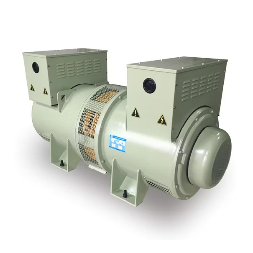
The Role of Alternating Current Generators (Alternators)
Often referred to as an AC generator, it acts as the alternator. This generator on the one hand has two basic components, with one being the rotating member or commonly referred to as the rotor, and the other the stationary armature which is the stator. The rotor is provided with magnetic poles, these poles are carried out by the iron core and the assembly is free to rotate in relation to the stationary stator. The stator on the other hand, is a stationary frame that contains the armature winding where voltage to the load is picked up as electromotive field develops due to the effect of the magnetic field.
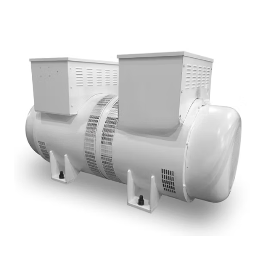
Indeed, alternators are very important and useful in power generation through power plants. They are the converters of mechanical energy—often derived from steam, water, wind or gas turbines— into alternating current hence making it ready for use in the power conduction grids. They are designed for long periods of operation and in a variety of circumstances. This is why they must be used for power supply purposes in a very limited scope.
On the other side, these engines are necessary in a vehicle systems. They are used to control the discharge of the battery and supply power to the various electronic components such as the illumination and information systems. Advancements in this direction have developed new energy-saving measures within their machines, such as avr and optimum load control, which are also known as the intelligent charging systems, as they are able estimate the required charging over time without undercharging or overcharging, thereby conserving fuel and charge.
Operational Logic of Rotary Frequency Converters
Rotary frequency converters work on the principle of a rotating apparatus turning electrical power of one frequency to another frequency. Operation is initiated with an input motor, which is driven by the frequency of the source. The motor is then connected through a mechanical link to a generator that generates electrical energy at the required output frequency. Precision frequency control due to the intrinsic design of the machine, makes it beneficial in a few applications such as aerospace and research. More so, rotary conversion is highly dependable due to the fact that simple and robust mechanical parts are used, hence there is a small need for delicate electronic devices within. This high level of dependability exempts them from use in places where accurate frequency checks are essential for sustenance.
Input Power and Initial Conditions
A rotary converter’s performance is primarily affected by the quality of the incoming electrical power, and the nature of the initial operating conditions. There is a need for the incoming power to be steady enough and within the prescribed voltage and frequency limits to ensure smooth running of the machine. Practically any errors in the power supply such as especially voltage sags, harmonic distortions and frequency fluctuations can subdue the converter’s amplification with stability. Moreover, the initial operating parameters such as the temperature of the surroundings and the intensity of the load, are extremely crucial for the converter. In such conditions as extreme temperatures, usage of additional cooling systems and certain types of materials become imperative so as to prevent overheating of the components.
Electrical and Mechanical Sequence Analysis
Electrical and mechanical sequence analysis includes a holistic study of the co-ordinated activities of the electrical circuits and the mechanical components within a system. In many application areas where timing and control have to be very precise, such as in robotics, industrial automation, and power industries, this is a critical step. By tracing the flow of electrical and mechanical events in sequence, bottlenecks, misalignments and inefficiencies can be detected by the engineers. Generally, sophisticated techniques are utilized, such as time domain analysis and state transition diagrams, to replicate more complex systems and forecast the system outcome. Analysis is also possible with the help of the technology’s advantages by use of up-to-date computation devices, and more complicated analysis is done to enhance the optimization of systems and ensure that they meet the operational standards that are required.
Stabilizing Output Frequency
The proper management of system frequency changes is an important procedure, with power plants, telecommunications and information processing systems as primary examples. Usually, such technological procedures require installation of precise control devices to address problems with the large signal distortion. One of the popular solutions is to use phase locked loops (PLLs) for frequency synchronization through the use of control signals.
The development of digital signal processing technology improves frequency stabilization significantly because it enables real-time usage of adaptive filtering algorithms to suppress noise and cancel interference. Also, FM modulation methods and compensation algorithms are used in order to bypass system parameters in the most efficient way and achieve output stabilization under variable input conditions. Rigorous procedures for validation and assessment of performance are also critical to measure achievements based on operational and regulatory requirements.
Industrial Applications & Use Cases
- Aerospace and Defense
This involves changing line power frequency (e.g., converting 60 Hz to 400 Hz) to be in alignment with the power requirements of the aircraft or military equipment and the associated foretold systems.
- Manufacturing
Often used in plants that provide machines specifically engineered for power frequencies common in other parts of the globe, ensuring gears are operable wherever there is electricity.
- Renewable Energy Systems
Mitigate frequency instability in the energy resources supply from both wind and hydropower sources to ensure that they meet the distribution requirements of the grid.
- Marine and Shipbuilding
Resolve the issue of onboard equipment power quality, which varies between the sources of the equipment and rectified power.
Aerospace Testing Scenarios
Thus, aerospace tests demand exceptional accuracy and regulations that are structured for the evaluation of products, systems, and cheap replicas of military structures. The theoretical model defines two use conditions of frequency converters, which are required to provide these or those electrical environments as though a research object were flying in the sky or in space on the basis of the declared technology or device. Hence, appropriate for testing avionic systems under different electrical strain levels and provide conformality to a wide range of power supply issues related to different countries surfaces, helping to regulate the logistic issues and ensuring the appropriate usage of expensive equipment.
Moreover, it was noted that the environmental simulation chamber of some aerospace testing facilities employs frequency converters to imitate power disturbances typical of extreme environmental conditions, e.g., high altitudes and quick weather transitions. Moreover, there is also a more specialized issue involving equipment operation resistibility under the influence of dynamic frequency operation through general and automated tests. Frequency converters also permit a repeatable and flexible power supply to be provided, thus helping electrical systems to meet the demanding standards like RTCA DO-160 or MIL-STD-704, followed in the aerospace sector. Consequently, this contributes towards the confirmation protocols aimed at ascertaining the safety, design and quality expectations which are crucial in the aerospace industry.
Marine Power Systems Utilization
Marine propulsion is indispensable for both commercial and military vessels of the contemporary era to ensure the power supply of most applications, including propulsion, shipboard equipment, auxiliary equipment in operations, is safe and does not fail, and such systems are seawater, high temperature, and vibration-resistant. A ship power generation system is divided between steering and automatic control, and power management functions use devices for frequency adjustment (known as VFD) and power storage structures and others to reduce power use in vessels.
In the maritime industry, there is a rapid increase in the adoption of advanced energy storage systems, especially lithium-ion batteries for electrically powered vessels, to the hybrid or completely electric versions, thereby reducing harmful exhaust emissions, thus increasing efficiency. They are additionally found in many gas turbines and combined-cycle systems that transform conventional power generation into intelligent power capability matching the vessel in size as well as operational relevance. Moving towards a more eco-friendly perspective, marine power systems such as airliners have placed strict requirements, for example, the IMO Tier III standards.
Reference Sources
- Synchronous Machine Field Excitation Utilizing a Single-Phase Matrix Converter
Read more here - Rotary Wireless Inductive Transmitter Powered by ZVS Resonant Converter
Read more here
Frequently Asked Questions (FAQs)
How does a frequency converter work to convert power from one frequency?
Generally, frequency converters function by converting the incoming alternating current power into direct current power by means of rectification, and then by using an inverter, it synthesizes the required frequency and voltage — this facilitates conversion of power at one frequency (for example, 50 Hz) to be at another frequency (for example 60 Hz or 400 Hz). In fact, recent developments in technology have seen the emergence of the solid state logic era in frequency converters. Frequencies and phase angles are controlled by power electronic devices only. Only one of the three phases of electricity comes into the frequency regulated loads or devices.
How do different converters work to produce three-phase power from a single phase?
There are several methods through which converters perform: on the one hand, rotary converters are equipped with both an engine and a generator which share the same axis, cultivating triple or three stage electric current, whereas conveying these amounts in static frequency inverter or electronic inverter to convert single phase ac energy with some form of a semiconductor switch is an altogether different perspective. Electro-mechanical rotary convertors, on the other hand, convert the ac power to mechanical in rotary form, which, in turn, again becomes an equivalent three-phase electrical power output, which is known to be beneficial during intense applications such as when running a switched reluctance three-phase motor.
What is a phase converter and when are phase converters used?
What defines a phase converter and helps match different eigenfaces to transform power? Commonly helpful in providing 3-phase power from a 1-phase source in situations where motor devices, etc., may need 3-phase power even though the service is not available. When a three phase pump operates with energy supply, single Phase will ultimately result in equipment failure. Phase converters are used in commercial establishments and locations without utility services to run equipment meant for 3-phase motors without extending the new service.
What is the rotary phase converter working principle?
An incandescent phase converter uses an idle motor as a rotary transistor to energize the motor under changing its energy directly into electrical vibration, making it a suitable device for producing three-phase electric power in preferred phase angles almost close to 120 degrees. A semi-credit condition unit can be done due to the most favorable construction of the motor and the withdrawal system in one system which enables low or no torque variations for motor outputs. And the rotor can be taken to the desired mechanical result in case it is deemed useful in that certain configuration.
