
It is a known fact that frequency converters can also be classified as step-up or step-down units due to the differing AC frequency conversion requirements posed in various industrial applications. Most plants that have imported electrical machinery often need to have frequency conversion devices that are built into the bottom or top of the machines. It is, therefore, critical to emphasize that a rotary frequency converter, which regulates the frequency of an electrical power supply, is not a new concept in the electric power industry. This article will describe the principles that underlie operation of the rotary frequency converter, the problems, benefits and other advantages when using this equipment. After reading the article, the reader will understand what rotary frequency converters consist of and why they are so necessary in today’s world.
Introduction to Rotary Frequency Converters
Rotary converters are machines used to convert electrical energy from one frequency to another. Rotary converters achieve this through mechanically coupling a generator and an electric motor. The motor will have operating frequency and the output of the machine a desired frequency. This is advantageous, particularly in appliances using different power standards, such as 50 Hz and 60 Hz. Rotary Converters are used in the conversion of 50hz to 60hz for that reason. Owing to their rugged design and dependable operation, rotary converters are commonly utilized in industrial services, along with transportation, particularly in the sectors of aviation and shipping, in order to ensure that the power supply remains stable and dependable throughout use.
Definition and Purpose of Rotary Frequency Converters
Rotary frequency converters are a type of electromechanical systems that have been designed to feed in electrical power but provide changes in its frequency, so as to suit the requirements of the operation of single or multiple individual pieces of equipment in various places. These devices convert frequency by means of an electric motor turning a generator to provide an output frequency different from the input frequency. This adjustment of the electrical power in the system allows for the machines to work even if the power system is of different frequencies such as 50 Hz and 60 Hz which are mostly used.
Recent advancements in materials and engineering have made rotary frequency converters more advanced than in the past. This has significantly increased means of improvement for efficiency, ease of maintenance and durability. They are able to cater for high power levels, an obvious necessity in areas of application deemed highly critical such as the aerospace industry simulation, various manufacturing processes as well as maritime operations where stable frequency is needed. In addition they ensure that the performance and the equipment’s safety is sustained by delivery of pristine power in the circuits very well protected from the effects of power issues. These points illustrate the important use of rotary frequency converters in harmonizing power frequency standards worldwide and supporting sustainable energy provision.
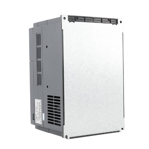
Key Components of a Rotary Frequency Converter
| Component | Description |
|---|---|
| Prime Mover | Provides mechanical energy to drive the system. |
| Alternator | Converts mechanical energy into alternating current. |
| Rotary Engine | Maintains consistent rotational speed and torque. |
| Cooling System | Regulates temperature during operation. |
| Control Panel | Offers operational controls and monitoring features. |
| Automatic Voltage Regulator (AVR) | Stabilizes output voltage efficiently. |
| Bearings | Reduces friction and supports rotary movement. |
| Lubrication System | Ensures smooth operation by minimizing wear. |
| Power Input/Output Terminals | Facilitates seamless electrical connections. |
| Frame and Enclosure | Protects components from environmental factors. |
Difference Between Rotary and Static Frequency Converters
| Key Parameter | Rotary Frequency Converter | Static Frequency Converter |
|---|---|---|
| Design and Components | Uses motor-generator set | Uses solid-state electronics |
| Energy Efficiency | Generally less efficient | High energy efficiency |
| Maintenance | Requires regular mechanical maintenance | Minimal maintenance required |
| Size and Weight | Bulkier and heavier | Compact and lightweight |
| Noise Level | Produces mechanical noise | Virtually silent operation |
| Startup Time | Longer startup time | Instantaneous startup |
| Durability | Durable under heavy loads | Sensitive to electrical surges |
| Initial Cost | Generally higher upfront cost | Typically more affordable |
| Power Quality | Handles load variations well | May need filters for stability |
| Applications | Suitable for large-scale operations | Ideal for precision, small-scale tasks |
Fundamental Concepts of Frequency Conversion
To alter the frequency of an electrical signal so that it is consistent with a particular device or system is what is basically known as frequency Conversion. The altering of the signal can be achieved through the application of a device called the frequency converter which is capable of varying the input or output frequency to the desired level. The primary objective of frequency conversion is to adapt the power source and the equipment in use, such that better output and performance are achieved. Frequency conversion is paramount in variable speed drives, solar power systems as well as aircraft power inverters. The parameters usually taken into consideration also encompass the input and output frequency variations, the dictates of the load, and conversion efficiency of the overall process.
Basic Principles of Frequency Conversion
Frequency conversion used in power electronics equipment requires the existence of an alternating current or the input AC to frequency convert to modulate different devices, commonly an induction coil. In this case, however, the waveform is modified to increase the frequency but the alterations in basically components are minimal. This processing usually is done with each other power electronic elements including diodes, transistors, and thyratrons. The recently available converter systems, therefore, employ state-of-the-art devices with improved performance. Such devices include, but are not limited to, power bipolar junction transistors (IGBTs), gallium nitride transistors (GaN), and silicon carbide (SiC).
When performing frequency conversion, it is important to consider a few crucial parameters such as total harmonic distortion (THD), power factor correction (PFC) and heat management. Minimizing the SVT value quite obviously occurs the elimination of any harmful contamination of the output signal which could disturb or damage appliances intended for laboratory and medical use. PFC is the harmonization of voltage and current waveforms in order to enhance the general power efficiency of the system. Advanced cooling technologies like integrated into the power, cooling devices effectively manage the temperature of the system and this is very important in large power applications due to concerns about heat.
How Frequencies Are Generated and Regulated
A number of methods are utilized to generate frequencies in the operation and control of devices, such as oscillation circuits, synchronization mechanisms and advanced regulation systems. Primary frequency generation starts with an oscillator, such as crystal oscillators or voltage-controlled oscillators (VCOs), which are used to generate a stable frequency. These oscillators use materials such as quartz to exploit favorable properties and achieve a stable output. Having been developed, the frequency generators are controlled with the use ofphase locked loops (PLL), which assist in attaining the final output frequency aligned with a reference signal.
This arrangement guarantees that the frequency is accurate and meets system requirements at all times, even when there are changes occurring due to disturbances or variations in input or output. Furthermore, the current applications of the digital signal processing (DSP) have greatly enhanced real-time control over the frequency deviations by measures which correct these deviations with fast and efficient methods. These systems are required in several sectors to accomplish functions such as in telecommunication, power systems, industrial processes, where accuracy and stability of performance is very attractive.
The Role of Rotating Elements in Frequency Conversion
Rotating mechanisms like synchronous machines and alternators play a key role in the process of frequency conversion. They mainly facilitate the linking of the input and output frequencies so as to enable the efficient conversion of electrical energy. A typical machine of this type works by maintaining a constant speed of turn which is a proportion to the system frequency, necessary to operate such equipment within specific energy conversion systems. The use of embedded rotary electrical converter technology based on advanced control topologies, such as cycloconverters and doubly-fed induction machines (DFIMs), improves performance and applicability.
With minimum changes into them, they perform the most important role in utilizing the continuous power frequencies ideal for shifting the rotary frequency levels during renewable power generation period such wind turbine input frequency modulation systems vacuum tubes. Such an approach consists of accessible materials and in extensive application of systems with up-to-date components like electronic parts.
Operational Mechanics of Rotary Frequency Converters
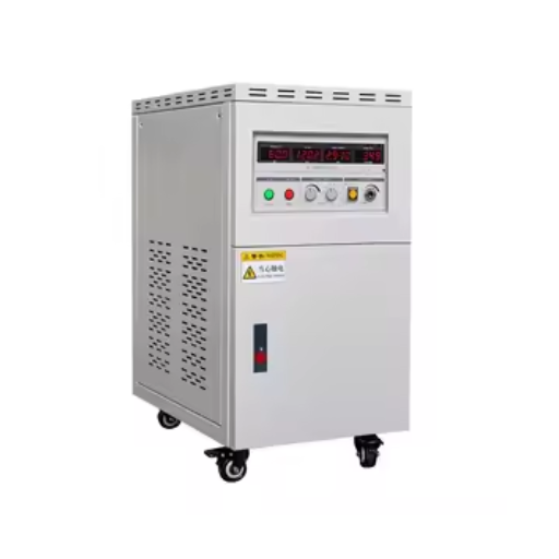
Rotary frequency converters utilize a motor in conjunction with a generator to function. The motor runs at a certain frequency, as long as there is power supplied, and it in turn runs the generator that will give an output frequency level that is very specific. These frequency converting systems use mechanical rotation to get the output frequency, a create power do not dip in very unfavorable conditions. Motor, generator as well as the coupling systems are the main elements within these systems; hence, they must all be properly designed to ensure effectiveness and long service life. The rotary systems are beneficial when it comes to applications with high power producing capabilities and rugged constructions because they can still perform even when the load fluctuates.
How Rotary Frequency Converters Work
Rotary frequency converters work by the natural energy transfer aspect through the input and output of the electric machine. It is good to identify the stages: the input motor, which is powered with electrical power that is normally the mains, and which applies an unconventional frequency incompatible with the target technology and subsequent process. Most motor applications use a motor to drive a generator or the output of the motor is needed at some other speed.
A motor-generator assembly shows good performance if it is highly calibrated and engineered, lightweight and resource-saving windings, quality ball bearing, and specialized cooling converge. Other technological improvements include usage of expert systems and vibration control in contemporary rotary converters. Thanks to his, it becomes possible to achieve the prescribed performance levels, even in unfavorable environments and/or under varying loading conditions, which are the most frequent areas of application of frequency modifying devices, e.g., for aerospace, marine, and in custom manufacturing.
Understanding the Rotary Converter Cycle
The conversion of electric power to the desired output frequency and voltage is achieved. When the rotary converter is started, an initial phase of the process is triggered by the production of the rotating magnetic field. The said field interfaces with the rotating part which then creates mechanical energy that later on is converted to electrical energy, but enhanced in a certain manner. In a system of this complexity, the amount of losses and conversions depends on the development of the materials and, certainly, science involved in the achievement of motor design, which assigns a lower electrical loss to a certain rotor and a higher electrical loss to a certain stator that has a high copper-concentration wire in the windings.
Endeavors have shown the importance of certain efficiency metrics in the description of the rotary converter systems. For instance, it could be seen that the energy coefficient of conversion has gone beyond 95%, indicating the usage of better insulating materials and determined heat removal techniques. Illustratively, employing current systems help detect and correct the load sway and converter state immediately, thus preventing or limiting expensive off-line periods and hence allowing active systems use for longer time spans. These achievements rather emphasize the significance of rotary machines while dealing with applications requiring high dependability and accuracy, such as aircraft power and data center power management.
Phase Conversion Process in Rotary Frequency Converters
Rotary frequency converters employ a time phase conversion process that incorporates mechanical and electromagnetic force to achieve highly precise output frequency and voltage corresponding to the input. In specified cases, the incoming current whose frequency is the source one is fed to the converter to miscellaneous engines by means of rotating parts such as rotor disks or flywheels. This movement is the key factor that relates to obtaining the desired major characteristics of the system from the input energy.
Furthermore, within the converter, the alternator unit which could be explained as per the crane machines’ terminology rotates with the rotating mass to enable the application of output power of the desired frequency and phase. Similarly, it is possible to convert single phase input power into three phase output, or to change the national utility frequency of 60Hz to 50 Hz in order to suit foreign equipment requirements. Such changes in the mode of operation also rely on how fast the rotor spins, how the stator winding is connected and the maximum permissible torque that can be transmitted to the shaft.
The development in the material and control systems have brought changes in the working of the machine. When we talk of the present rotary frequency converters, they are made up of well-machined, and finely-tuned components and dynamic stability structures aimed at reducing any possible mechanical losses. These transformers can work together with intelligent control systems to monitor different values of the load being fed by the frequency output and adjust the frequency output appropriately. Furthermore, restraining the harmonic distortion is possible as better filtering systems are employed, further working to eliminate distortions and reverting the signal back to a more clean wave. It is with these particular developments that the use of rotary frequency changers in these systems is very necessary.
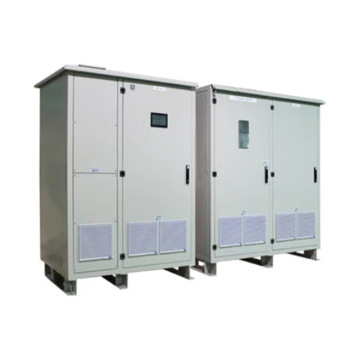
Applications of Rotary Frequency Converters
Industries that require precise power adjustments and maintain system stability require all the services required for interstate power transmission. Reasons for which use of such technologies is important in aviation are: use of the technology as the ground source which helps the systems of the aircraft to work well during their maintenance/repairs and quality checks especially at the preflight phase. Moreover, such angles as in generating plants where different frequency standards are adopted for particular tools in the manufacturing unit s and those that relate to the national grid. Frequent use of converters can also be observed in research laboratories which have commonly been adopted for such purposes.
Industrial Applications of Rotary Frequency Converters
Rotary frequency converters have gone through major changes, enhancing their capability in recent decades due to the advent of engineering and power electronics. Advanced servo converters allow these devices to output the required frequencies with a high degree of precision which is a necessity in efficient industrial processes. An example would be in manufacturing that goes above normal production levels, especially for the aerospace and automotive industries – here, they count on CNC machines and automation that will ask for an uninterrupted and clean power supply.
In addition, there has been a growing trend recently where constantly increasing rotary frequency converters are used in the context of renewable energy. They play an important role in supporting the dependent transition of variable renewable energy sources to the grid by controlling the power output so that it matches the local grid frequency. This is particularly valuable in the wind farms and photovoltaic systems, and enhances the useful grid performance and immunity to any form of disturbances. It is the appropriate balance between reliability, economic performance and flexibility, that makes rotary frequency converters an indispensable component of the current industry infrastructure.
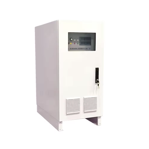
Use in Renewable Energy Systems
One of the key areas of using rotary frequency converters is the incorporation of renewable energy systems into the power grid. Thus, in the case of wind power, the rotation of turbine blades in most cases leads to some electric frequencies that are not regular. In such cases, rotary converters prove to be very useful in that they come in to iron out these swings, making it easy to make power that is in phase with the standard grid without losing energy. Similarly, solar photovoltaic systems, which produce electricity in relation to the change of solar irradiation, experience significant advantages due to the applicability of rotary frequency converters that provide uniform continuous energy conversion.
The state of rotary frequency converter technology has been in constant evolution in the recent past, such that these technologies include variable control systems and energy-efficient components, which have further enhanced their performance. These are abilities which deliver increased efficiency of power transmission and more accurate establishment of the frequency stability, and are thus essential for the smooth transformation to more sustainable energy practices worldwide.
Role in Electric Motor Drives
The applications of rotary frequency converters in the control of electrical machines especially for electric motor drives, wherein high performance speed and torque control is dictated pose one of the very pertinent and most difficult questions involving energy engineering. Basically, what it does is convert fixed frequency input power to a variable output frequency, offering motors the flexibility of operation as demanded efficiently and adaptively. This is a particularly important characteristic in industries such as manufacturing, aerospace and transportation where the speed and reliability of motor operated machines are at the core.
Enhanced running conditions, added mechanical tension relief, and less power consumption are just some of the advantages foreseen by this development. It is to be mentioned that modern ferrorotating convertors perform extra safety monitoring and fault alarms, which secure correct control execution and minimize any non-utilizing downtimes due to mechanical defects or failures. These improvements illustrate their significance in industrial automation and other energy-saving presentations.
Maintenance Practices for Rotary Frequency Converters
- Routine Inspections
Conduct regular checks regarding any sort of wear, overheating, or any unexpected vibration’inmovement components and with power connections to pick out any possible issues, if they occur, early on. - Cleaning
Ensure the cleanliness of the housing, the smoothness of operating surfaces, the presence of dust and debris that can accumulate on the vent holes or internal sections, and thus curb the ventilation and overheating. - Lubrication
It is necessary to occasionally provide lubricants for the operation of the respective component as advised by the manufacturer’s user manual so as to reduce the wear and prevent unnecessary mechanical disturbances. - Testing and Calibration
Conduct load testing periodically, with focus on accuracy during the output of voltage and frequency, controls are calibrated as such to sustain the level of effectiveness. - Cooling System Maintenance
Ensure the fans, for example, or liquid cooling is in good health so as to be able to control the escalating system temperatures without failing. - Component Replacement
Regarding preventive maintenance, items that have been worn out or deteriorated, including bearings or filters, must be replaced so as to prevent surprise failures and avoid expensive downtimes.
Best Practices for Extending Converter Life
- Adhere to Manufacturer Guidelines
All scheduled maintenance, operational conditions and precautions as outlined in the manufacturer’s manual must be strictly adhered to for the proper operation of the converter. This is to minimize wear and assure long term performance. - Implement Real-Time Monitoring Systems
Employ some automation systems to spy on temperature, load levels and voltage bewebopar fluctuations. Early discovery of any defects that can be seen as anomalies will indicate that failure may be impending and will enable to take the necessary corrective action even before the failure has occurred and resulted into tremendous shortcomings. - Perform Load Balancing
Prevent overutilization of the transcoder and distribute the load within the frame dynamics. Staying for long periods at or above top rated capacities provokes wear and tear on the critical components of the tool. - Ensure Environmental Control
Keep the temperatures, relative humidity and cleanliness of operation environment under the prescribed limits. Dust and high temperatures usually drag down the effectiveness of converters, thus helping to cool them with proper ventilation and air filtering is quite necessary. - Upgrade Firmware and Software
Make sure that the firmware and related software used to control the converters are updated regularly to cope with technological changes, and to take advantage of performance gains or correct software defects or problems introduced by the device manufacturer. - Utilize Predictive Maintenance Strategies
Perform predictive maintenance and real-time diagnostics for cycle-accurate monitoring of each component state. That allows to make servicing before failure efficiently making system survive beyond the limits of the guaranteed portions.
When to Seek Professional Maintenance Services
Knowing when to call in professional services largely requires an assessment of the scale of the problem, the specific equipment to be used, and above all, the dangers of inadequate handling which may be posed. The user could be proactive if the following signs transpire: the system that was previously malfunctioning several times, even though proper or regular maintenance was done, abnormal noise and or vibration, which indicates possible mechanical failure, among others, and error messages, which mean that the faults or mistakes are there and are potentially destabilizing.
Called professional help again, systematic equipment such as thermal imaging and ultrasonic testing, which is hard to interpret accurately from the dataset, is used. Operations, devices or any other integral machine parts that are prone to breakage or are worn out must be fixed more time and tools. Hiring experts allows the corporate safety standards to be met, and more importantly, introduces changes to the technical settings that will improve the life cycle and function of equipment in a more efficient, well-structured, and transparent way.
Reference Sources
Frequently Asked Questions (FAQs)
What is a rotary frequency converter?
Rotary frequency converter is an electric converter consisting of an induction motor and a generator mounted on the same shaft so as to change the frequency of electrical power. It is the electrical equipment which converts ac into rotary mechanical power and after that converts it back to ac at the desirable frequency. Most of the times, these systems are used for creating three-phase electric power when the frequency of the utility power or any other phase is not desirable. Examples include providing 400 Hz and other frequencies for avionics systems and industrial equipment.
How does a frequency converter work?
The job of a frequency converter is when a generator is powered by an electric motor so that it works at the frequency of the power source. This principle of frequency converter operation seeks to determine the rotor speed and the amount of poles in the generator in which the rotational speed of the rotor will yield the required frequency (for example poles count multiplied by the speed of the rotor relationship). In the rotary converter, both the motor and generator are designed with a single shaft and energy is exchanged by. Power is also divided into two converters, solid and rotary type systems. The solid type, being very simple, consists of simple rectifier and inverter stages connected back-to-back in order to make the AC power frequency variable. In such cases both stages are working throughout.
What is the difference between a phase converter and a rotary phase converter?
A phase converter is a device that converts single-phase power into three-phase alternating current power by integrating an idler, an induction motor and a generator to create rotary power. It makes use of the motor’s flux and the movement of the motor to create the third phase of 120 degrees relative to the other two. On the other hand, it has been discovered that the solid state methods of phase conversion are more efficient by increasing the power being delivered by rectifier and electronics to synthesize lost power. These are the approaches that the rotary units opted to improve on the areas where solid states could not deliver as required by the engineers.
Why do converters work to produce three-phase power?
In a phase converter, the geometry and the necessary angles are generated to give an output in 3-phase system, always making sure that the phase angles are separated by 120 degrees. With rotary designs, the motor and the generator are installed on the same shaft and the rotational speed can be used to set the rotational frequency and the load sharing, we deriving balanced three phase power for the motors with several number of poles. This is especially needed in cases where three-phase electric power is required for equipment that expects variable-frequency or even high-frequency power, such as 400 Hz power frequency.
