
In 2023, a Permian Basin operator running 50 fixed-speed electric submersible pumps faced a problem that sounds familiar to every production engineer: electricity costs were eating 18% of operating budget, and voltage sags during motor starts were damaging transformers twice a quarter. The operator installed VFDs on every pump. Within 12 months, energy consumption dropped 28%. Transformer failures fell to zero. And the project paid for itself in 22 months. The secret was not just adding VFDs. It was selecting the right topology for artificial lift.
You already know that a high voltage frequency converter oil and gas installation can cut energy bills and extend equipment life. What is harder is knowing exactly which drive type, topology, and specification your upstream, midstream, or downstream application requires. The wrong choice creates harmonic issues, cable failures, or project delays that erase every dollar of savings.
This guide focuses on oil and gas applications and selection. For a full technical foundation on drive types, voltage classes, and operating principles, see our complete guide to high voltage frequency converters. By the end of this article, you will know which drive topology matches your application, when electrification beats gas turbines, and how to specify voltage class, cooling method, and harmonic mitigation for offshore and onshore projects.
Key Takeaways
- Pumps account for ~40% of oil & gas VFD demand; compressors are the fastest-growing segment
- VFD/motor systems achieve ~95% efficiency versus ~36% for industrial gas turbines
- DFE is cost-effective for pumps; AFE for regeneration and low harmonics; LCI for very large synchronous compressors
- Offshore platforms require water-cooled designs, compact footprints, and strict harmonic management
- Typical energy savings range from 15-30% for pumps, 12-24% for compressors, and 18-28% for fans
- ESP drives require special long-cable output filtering for distances up to 30 km
What Is a High Voltage Frequency Converter in Oil and Gas?
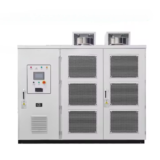
A high voltage frequency converter in oil and gas is a variable frequency drive (VFD) rated for medium or high voltage classes that controls the speed and torque of large electric motors driving pumps, compressors, fans, and extruders across upstream production, midstream transport, and downstream refining operations. Unlike standard low-voltage drives, these systems operate at 2.3 kV to 13.8 kV and handle power levels from hundreds of kilowatts to more than 90 MW in large LNG liquefaction trains.
Before selecting a drive for your oil and gas application, confirm you understand medium voltage VFD fundamentals so you can interpret specifications correctly.
Defining High Voltage and Medium Voltage Drive Classes
Voltage terminology in the drive industry is slightly inconsistent. IEC standards define “medium voltage” as 1 kV to 35 kV, while NEMA uses “medium voltage” for 2.3 kV to 69 kV. In practice, oil and gas VFDs cluster around these standard classes:
- 2.3 kV and 3.3 kV: Common for offshore platform motors and smaller onshore pumps
- 4.16 kV: Widely used in North American refinery and petrochemical applications
- 6.6 kV and 6.9 kV: Standard for large pipeline pumps, water injection, and compressors
- 11 kV and 13.8 kV: Used for very large synchronous motors in LNG and pipeline service
Power ratings follow the application. An ESP drive on an onshore well might need only 300 kW. A main liquefaction compressor could need 50 MW or more. Matching voltage class and power rating to the motor nameplate is the first non-negotiable step in specification.
Why Oil and Gas Operations Need Variable Speed Control
Fixed-speed motors run at full speed regardless of demand. In oil and gas, that mismatch is expensive. A pipeline pump running at full throttle against a partially closed valve wastes energy as heat and noise. A compressor cycling on and off to match gas flow suffers mechanical stress and inconsistent output. A cooling tower fan running flat out in winter over-cools the process and wastes power.
Variable speed control matches motor output to process demand. That single capability delivers three benefits that drive VFD adoption across every segment of the industry. First, energy consumption falls because motor power scales with the cube of speed for pumps and fans. Second, mechanical stress drops because the drive provides soft starting and controlled acceleration. Third, process control improves because flow, pressure, and temperature can be held precisely at setpoints.
Upstream Applications: Production and Artificial Lift
Upstream operations, exploration and production, present some of the most technically challenging VFD applications. Wells are often remote. Power quality is poor. Motor cables can stretch for kilometers. And downtime costs thousands of dollars per hour.
Electric Submersible Pumps (ESP) and Long-Cable Challenges
Electric submersible pumps account for a significant share of upstream artificial lift. An ESP is a multi-stage centrifugal pump installed downhole, driven by a three-phase motor that can sit 1,000 to 3,000 meters below surface. The drive sits on the surface. The cable between them is long, expensive, and electrically stressful.
Long motor cables create voltage reflection. When a VFD switches its output transistors rapidly, the sharp voltage edges travel down the cable and reflect back from the motor terminals. The reflected wave can double the voltage at the motor, damaging insulation. This problem worsens with cable length. Onshore ESPs might use 2 km of cable. Offshore ESPs can use 30 km of cable from platform to subsea completion.
The solution is output filtering. Drives for ESP duty must include either dv/dt filters, sine-wave filters, or specially designed inverter-duty motors with reinforced insulation. Some manufacturers, including Rockwell Automation with its PowerFlex 7000 series, advertise ESP cable capability to 30 km with the right filter package. Specifying a standard pump drive without output filtering for ESP duty is a common and costly mistake.
Water Injection and Production Pumps
Water injection maintains reservoir pressure and improves recovery rates. Injection pumps are large, continuous-duty centrifugal pumps that move produced or seawater into the formation. They run for years without shutdown. That makes efficiency critical.
A VFD on an injection pump adjusts flow to match reservoir demand. When injection requirements drop, the pump slows rather than throttling with a valve. Energy savings of 15% to 25% are typical. Payback periods of 18 to 30 months are common, depending on local electricity prices and pump duty cycle.
Production pumps on the surface move crude from wellhead to gathering stations. These applications are less demanding than ESPs but still benefit from soft starting and flow control. Many Permian Basin operators have retrofitted fixed-speed production pumps with VFDs as part of field electrification programs.
Gas Lift and Compression
Gas lift is employed to inject high-pressure gas down the hole to reduce the density of the fluid and help crude flow to the surface. Compressors for gas lift service are generally of a much smaller size than the pipeline or LNG compressors but have to run continuously. Using variable frequency drives (VFDs) for controlling the gas lift compressor allows gauging of the precise injection pressures and flow which in turn increase well profitability while at the same time reducing compressors’ lives.
Midstream Applications: Transport and Liquefaction
Midstream infrastructure moves hydrocarbons from production to processing. Pipelines span continents. LNG plants convert gas to liquid for marine transport. Both depend on large rotating equipment that is increasingly driven by VFD-controlled motors rather than gas turbines.
Pipeline Pump and Compressor Stations
Pipeline pump stations maintain flow and pressure over long distances. A crude oil pipeline from the Permian Basin to the Gulf Coast might have 20 pump stations spaced every 50 to 100 miles. Each station has multiple large pumps, historically driven by gas turbines or fixed-speed motors.
Replacing gas turbines with electric motor plus VFD packages is one of the fastest-growing trends in midstream infrastructure. The driver is economics. A VFD/motor system achieves roughly 95% electrical efficiency from grid to shaft. An industrial gas turbine achieves roughly 36% thermal efficiency. At part load, the gap widens because turbines suffer rapid efficiency loss below 80% rated load, while VFD/motor systems maintain high efficiency across a wide speed range.
In 2022, a North Sea drilling contractor replaced aging gas turbine-driven mud pumps with electric motor plus VFD packages. The drives reduced energy consumption by 32% and eliminated the mechanical shock loads that had caused three gearbox failures in two years. The payback was 14 months.
The newest pipeline projects have seen synchronous electric motors up to 8,200 rpm driven by MV drives replace geared compressor trains. This integrated motor and drive package eliminates gearbox maintenance and simplifies the situation, all-round, compared to turbine-driven or geared alternatives.
LNG Liquefaction Trains and Cryogenic Compressors
LNG liquefaction is among the most power-intensive processes in industry. A single liquefaction train can require 100 MW or more of compression power. Refrigerant compressors, mixed refrigerant compressors, and boil-off gas compressors all operate at variable conditions that make VFD control valuable.
TMEIC’s TMdrive-XL85, for example, is rated to 90 MW at 7.6 kV for LNG compressor duty. These are not off-the-shelf products. They are engineered systems where the motor, drive, coupling, and compressor are designed as an integrated package. The drive topology is typically LCI or AFE, selected based on harmonic requirements, regeneration needs, and grid code compliance.
For buyers evaluating LNG drive packages, the specification process is different from standard industrial VFD procurement. Performance guarantees cover the complete motor-drive-compressor system, not just the drive. Factory acceptance tests simulate actual liquefaction load profiles. And project lead times can extend to 24 months or more.
Booster Stations and Storage
Booster stations raise pressure in distribution pipelines or feed gas into storage facilities. These applications are smaller than mainline stations but more numerous. Standardized VFD packages in the 1 to 5 MW range are common. DFE topology is usually sufficient because booster pumps rarely require regeneration and harmonics can be managed with 12-pulse or 18-pulse rectifier configurations.
Downstream Applications: Refining and Processing
Downstream operations convert crude oil into fuels, chemicals, and petrochemical products. Refineries and petrochemical plants are dense with pumps, compressors, fans, and mixers. Many of these have run on fixed-speed motors for decades. Retrofit opportunities are substantial.
Refinery Process Pumps and Compressors
A large refinery can have 500 or more process pumps. Crude charge pumps, product pumps, circulation pumps, and utility pumps all move fluids against varying head and flow requirements. Adding VFDs to the largest 20% of pumps often captures 60% or more of the available energy savings because pump power scales with the cube of speed.
Refinery compressors handle hydrogen, fuel gas, and process vapors. Hydrogen compressors in hydrocracking and hydrotreating units are particularly critical. Unplanned shutdowns cost millions. VFDs provide controlled starting, surge avoidance, and precise throughput matching that improves reliability.
Refinery grids often have strict harmonic limits. Multiple VFDs running on the same bus can create harmonic distortion that affects sensitive control equipment. Active front end (AFE) drives or 12/18-pulse DFE configurations are often specified to meet IEEE 519 compliance without external filters.
Cooling Towers and Air Separation
Cooling towers reject waste heat from refining processes. Fans are classic variable-torque loads where VFDs deliver excellent returns. A cooling tower fan running at 80% speed uses roughly half the power of a fan running at full speed. Savings of 18% to 28% are typical, with payback periods often under 18 months.
Air separation units produce oxygen, nitrogen, and argon for refining and petrochemical use. Main air compressors and booster compressors are large, constant-torque loads. VFD control allows production rate adjustment without inefficient blow-off or recycle. Many air separation plants also recover energy through expansion turbines, creating opportunities for AFE drives that regenerate power back to the grid.
Petrochemical Extruders and Mixers
Extruders in polymer plants require high starting torque and precise speed control. VFDs replace DC drives and mechanical variable-speed drives in many modern plants. The benefits include better speed stability, reduced maintenance, and improved product consistency. Petrochemical extruders often operate in hazardous areas, so the drive enclosure and certification must match the area classification.
Drive Topology Selection for Oil and Gas
The drive topology determines how the VFD converts incoming AC power to variable-frequency output. Each topology has different cost, efficiency, harmonic, and regeneration characteristics. Choosing the wrong topology for your application can create grid code violations, excessive heat, or unnecessary expense.
Diode Front End (DFE): The Standard for Pumps
The diode front end is the most common and cost-effective topology. AC input passes through a diode rectifier to create a DC bus. An inverter section then converts DC back to variable-frequency AC for the motor.
DFE drives are simple, reliable, and inexpensive. They are the default choice for pump and fan applications where regeneration is not required and harmonics can be managed with multipulse rectifiers or passive filters. Most pipeline booster pumps, cooling tower fans, and water injection pumps use DFE topology.
The limitation is that DFE cannot regenerate power back to the grid. If your application involves frequent braking or downhill pumping, DFE wastes energy in brake resistors. Harmonic distortion is also higher than AFE unless 12-pulse or 18-pulse rectifiers are used.
Active Front End (AFE): When Regeneration and Low Harmonics Matter
An active front end replaces the diode rectifier with an active IGBT-based rectifier. This allows bidirectional power flow, meaning the drive can return energy to the grid during braking or overhauling loads. It also draws nearly sinusoidal current from the grid, achieving low harmonic distortion without external filters.
AFE is the right choice when:
- Your application requires regeneration (downhill pumping, crane hoists, test stands)
- Grid codes impose strict harmonic limits (offshore platforms, European refineries)
- You want to avoid the cost and space of 12-pulse transformers or passive harmonic filters
- Power quality is critical because sensitive control equipment shares the same bus
The downside is cost. An AFE drive costs 20% to 40% more than an equivalent DFE drive. For applications that do not need regeneration, the premium is hard to justify unless harmonic compliance is mandatory.
Cascaded H-Bridge (CHB): Modular and Transformerless
Cascaded H-bridge drives use a series of low-voltage power cells connected in series to produce medium voltage output. Each cell has its own isolated secondary winding on the input transformer. The cells switch in sequence to build a stepped sine wave with very low harmonic content.
CHB drives are popular in the oil and gas industry because they offer:
- Very low input harmonics without AFE cost (typically <3% THD with many cells)
- High redundancy (a failed cell can be bypassed, allowing continued operation at reduced capacity)
- Near-sinusoidal output that is gentle on motor insulation and bearings
- Transformer isolation that protects the motor from common-mode voltage
The tradeoff is physical size. The input transformer for a CHB drive is large and heavy. On offshore platforms where space and weight are constrained, CHB may not fit. For onshore installations where footprint is less critical, CHB is often the best balance of performance, reliability, and cost.
LCI and CSI: Very Large Synchronous Motors
Load commutated inverters (LCI) and current source inverters (CSI) are used for very large synchronous motor drives, typically above 10 MW and up to 90 MW. These topologies use thyristors rather than IGBTs and rely on the motor’s back-EMF for commutation.
LCI drives have been the standard for large LNG compressors, pipeline compressors, and refinery air compressors for decades. They are proven, efficient, and capable of extremely high power. The disadvantages include limited speed range (typically 50% to 100%), inability to run induction motors, and higher harmonic output that requires filters.
For new projects, voltage source inverter (VSI) technologies with IGBTs are increasingly displacing LCI because they offer better speed range, lower harmonics, and compatibility with both induction and synchronous motors. However, for the largest synchronous compressors in existing plants, LCI remains common.
Quick Topology Decision Table
| Application | Power Range | Recommended Topology | Why |
|---|---|---|---|
| ESP pumps, water injection | 200 kW – 5 MW | DFE or CHB | Cost-effective, proven |
| Pipeline pumps (mainline) | 5 – 30 MW | CHB or AFE | Low harmonics, high reliability |
| LNG compressors | 20 – 90 MW | LCI or AFE VSI | Proven at very high power |
| Refinery process pumps | 200 kW – 10 MW | DFE (12-pulse) or CHB | Balance of cost and performance |
| Cooling tower fans | 50 kW – 2 MW | DFE | Simple, low cost, effective |
| Downhill/regenerative | 1 – 20 MW | AFE | Energy recovery, grid compliance |
For a broader framework on vetting suppliers for oil and gas projects, see our manufacturer evaluation guide.
VFD vs Gas Turbine: The Electrification Decision
The oil and gas industry is in the middle of a large-scale electrification trend. Operators are replacing gas turbine-driven rotating equipment with electric motor plus VFD packages. The driver is not environmental ideology. It is straight economics.
Efficiency Comparison: 95% vs 36%
A modern VFD and motor system converts roughly 95% of electrical energy from the grid into mechanical work at the shaft. An industrial gas turbine converts roughly 36% of the fuel’s chemical energy into shaft work. The remaining 64% is lost as waste heat and exhaust.
At part load, the difference is even more dramatic. Gas turbines suffer rapid efficiency loss below 80% rated load. A turbine running at 50% load might drop to 25% efficiency. A VFD/motor system running at 50% speed still maintains roughly 92% to 94% efficiency. For applications with highly variable throughput, the electrification case is overwhelming.
The Permian Basin ESP example from the introduction illustrates this perfectly. The operator did not just save energy. They eliminated transformer damage caused by voltage sags during across-the-line motor starting. Soft starting from a VFD reduces inrush current by 60% or more compared to direct-on-line starting.
Emissions, Noise, and Maintenance
Gas turbines emit NOx, CO, and CO2 at the point of use. In an era of tightening emissions regulations and ESG reporting requirements, eliminating onsite combustion is increasingly attractive. Electric drives produce no local emissions. The emissions are shifted to the power generation source, where they can be controlled centrally or offset with renewable generation.
Noise is another factor. Industrial gas turbines operate at 100 to 120 dB and require acoustic enclosures. Electric motors are significantly quieter, reducing hearing protection requirements and community complaints.
Maintenance intervals tell a similar story. A gas turbine typically requires major overhaul every 25,000 to 50,000 operating hours. An electric motor can run 100,000 hours or more with only bearing inspections. VFDs have no moving parts and require minimal maintenance beyond cooling system checks and capacitor replacement every 10 to 15 years.
When Turbines Still Make Sense
Most buyers assume that replacing a gas turbine with an electric motor plus VFD is always the right choice. In reality, turbines still make sense for remote locations without grid power, for very high-speed applications above 10,000 rpm, and where waste heat recovery improves overall plant efficiency. The electrification decision requires a site-specific analysis, not a blanket recommendation.
If your facility has no grid connection, building transmission lines to bring in power may cost more than the fuel savings justify. If your process needs mechanical speeds above 10,000 rpm, turbines or expanders may be the only practical option. And if your plant can use the waste heat for process heating or cogeneration, the turbine’s overall energy utilization improves significantly.
Ready to compare electrification economics for your specific project? Contact our engineering team for a TCO analysis.
Offshore Platform Design Considerations
Offshore platforms impose constraints that onshore projects rarely face. Space is measured in square meters, not acres. Weight affects platform structural load and stability. And every kilogram of equipment must be lifted by crane or helicopter.
Space, Weight, and Cooling Constraints
Air-cooled drives need airflow. On a crowded platform, ducting cooling air in and out of an electrical room is difficult and expensive. Water-cooled drives are the standard for offshore MV applications because they reject heat through a compact water-to-seawater heat exchanger rather than large air ducts.
Water-cooled drives also reduce the electrical room HVAC load, saving additional space and power. The tradeoff is a more complex cooling system with pumps, heat exchangers, and potential seawater corrosion. For large platforms with multiple drives, the water-cooled approach almost always wins. For small platforms with one or two drives, air-cooled may still be simpler.
Footprint matters too. A cascaded H-bridge drive with its input transformer can occupy twice the floor space of an equivalent AFE drive. On platforms where every square meter costs thousands, that difference affects project economics. Multiple VFDs on a single platform grid can create harmonic distortion. See our MV drive power quality guide for IEEE 519 compliance strategies.
Harmonic Management on Platform Grids
Offshore platforms generate their own power, typically through gas turbine generators. The platform electrical grid is small and stiff, meaning it has low short-circuit capacity relative to load. That makes the grid sensitive to harmonic distortion from VFDs.
A single large VFD on a small platform grid can push total harmonic distortion above acceptable limits. The result is overheating of generators and transformers, nuisance tripping of protective relays, and interference with control and communication systems.
For offshore projects, harmonic analysis is mandatory during the design phase. The analysis models the entire platform grid, including generators, transformers, cables, and all VFD loads. Based on the results, the designer selects 12-pulse or 18-pulse DFE, AFE, or CHB topology and may add harmonic filters. Skipping this analysis is a common cause of commissioning delays and costly retrofits.
Hazardous Area Integration (ATEX/IECEx)
Offshore platforms have classified hazardous areas where explosive gas mixtures may be present. VFDs installed in these areas must carry ATEX or IECEx certification. Even drives located in safe electrical rooms may need to meet certain requirements if they control motors in hazardous areas.
The drive itself is rarely installed inside a hazardous area. Instead, it sits in a safe electrical room and connects to the motor through certified cable glands and seals. However, the drive’s output filtering, grounding, and fault protection must be designed with the hazardous area installation in mind. For hazardous area certification details, see our explosion-proof frequency converter guide.
Energy Savings and ROI by Application
Energy savings are the primary economic justification for VFD investment in oil and gas. But savings vary by application, duty cycle, and baseline efficiency. Buyers who understand the numbers can build stronger business cases.
Quantified Savings: Pumps, Compressors, and Fans
Pumps are the largest application and often the most profitable. Centrifugal pumps follow the affinity laws: flow is proportional to speed, head is proportional to speed squared, and power is proportional to speed cubed. That cubic relationship means a 20% reduction in speed cuts power by nearly 50%. In practice, system inefficiencies reduce this slightly, but savings of 15% to 30% are typical for pump VFD retrofits. Highly variable-flow systems can approach 50% savings.
Compressors save less than pumps because their load curves are steeper and minimum speed limits are higher. Savings of 12% to 24% are typical for centrifugal compressors with variable throughput. Reciprocating compressors benefit mainly from soft starting and load balancing rather than speed variation.
Fans and cooling tower blowers follow the same affinity laws as pumps. Savings of 18% to 28% are common because fan systems often operate well below maximum flow for much of the year.
Payback Periods and TCO Analysis
The global VFD market in oil and gas was valued at approximately USD 2.91 billion in 2024 and is projected to grow at a compound annual growth rate of 6.7% to roughly USD 5.09 billion by 2033. North America led revenue in 2023-2024 with approximately 35.4% market share, driven by Permian Basin ESP electrification.
VFD retrofits often show payback periods of roughly 2 years and internal rates of return exceeding 15%. New project economics are even better because the incremental cost of specifying a VFD instead of a fixed-speed motor is small compared to the total project cost.
Total cost of ownership analysis should include:
- Energy savings over the project life
- Reduced maintenance (soft starting, no throttling valves)
- Extended motor and driven equipment life
- Avoided downtime from electrical failures
- Potential utility rebates for energy efficiency
- Residual value at project end
When these factors are included, the business case for VFDs in most oil and gas applications is compelling.
For a deeper technical breakdown of high voltage VFD application standards, see our high voltage VFD applications guide.
Frequently Asked Questions
What voltage class should I specify for an oil and gas VFD?
Match the motor nameplate voltage. Common classes are 2.3 kV, 3.3 kV, 4.16 kV, 6.6 kV, and 6.9 kV. For very large motors above 10 MW, 11 kV or 13.8 kV may be used. Do not specify a drive voltage different from the motor voltage.
How do I handle long motor cables for ESP applications?
Specify output filtering. Dv/dt filters protect against fast voltage edges for cables up to roughly 500 meters. Sine-wave filters are needed for longer cables and provide the cleanest output waveform. Verify that the drive manufacturer certifies the filter for your specific cable length and motor type.
Can one VFD start and synchronize multiple pipeline pumps?
Yes, with synchronous transfer bypass. The VFD starts and accelerates the first pump to synchronous speed, then transfers it to the line while the VFD starts the second pump. This reduces the number of drives needed in multi-pump stations. Rockwell’s PowerFlex 6000T and TMEIC’s TMdrive families both support this function.
What is the typical payback period for a VFD retrofit on a refinery pump?
Payback periods of 18 to 30 months are typical for large refinery pumps running variable duty cycles. Pumps with high operating hours and significant throttling valve losses show the fastest payback. Utility rebates can shorten payback further.
Should I choose air-cooled or water-cooled for offshore?
Water-cooled is usually better for offshore platforms because it reduces electrical room size, eliminates large air ducts, and handles high ambient temperatures more effectively. The tradeoff is a more complex cooling water system. For small platforms with one or two drives, air-cooled may still be simpler overall.
Conclusion
Selecting a high voltage frequency converter oil and gas application is not a one-size-fits-all decision. Upstream ESP pumps need output filtering for long cables. Midstream pipeline stations need topology choices that balance efficiency, harmonics, and regeneration. Downstream refineries need drives that integrate into complex process control systems. Offshore platforms need water-cooled, compact, harmonically clean designs.
The electrification trend is accelerating. VFD/motor systems now offer roughly 95% efficiency against roughly 36% for gas turbines. Energy savings of 15% to 30% for pumps and 12% to 24% for compressors translate to payback periods often under two years. But the benefits go beyond energy: reduced maintenance, better process control, lower emissions, and quieter operation.
Match the topology to the application. Quantify the ROI with site-specific data. Treat offshore as a system integration challenge, not just a drive purchase. And remember that the cheapest drive is rarely the lowest total cost.
Shandong Electric manufactures power conversion equipment for industrial, mining, and energy applications, including our 400Hz frequency converter for ground power systems. For a customized high voltage frequency converter oil and gas solution, contact our engineering team today.
