
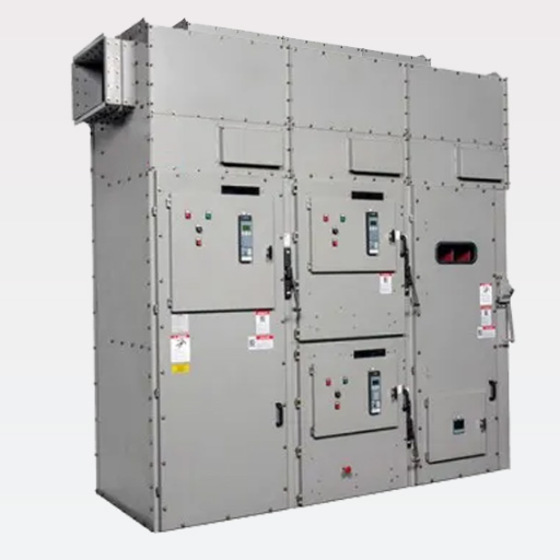
A medium voltage motor control center (MCC) is an assembly of one or more enclosed sections having a common power bus and containing principally vacuum contactor or circuit breaker motor starters rated from 1 kV to 15 kV. Proper MV MCC design and specification requires correct bus sizing, arc-resistant classification, NEMA enclosure selection, and spare capacity planning to ensure safe operation and room for future expansion.
An EPC engineer in Southeast Asia submitted a medium voltage MCC specification for a chemical plant expansion. The package was 40 pages, professionally formatted, with every clause in place. The winning vendor priced the job, manufactured the assembly, and shipped it to site.
During commissioning, the engineer discovered the main horizontal bus was rated for 1,200 amperes. But with all eight pumps running and three soft starters ramping simultaneously, the diversified peak current hit 1,480 amperes. The bus was undersized by nearly 25%.
The root cause was simple. The engineer had summed every motor’s full-load current to size the bus. No diversity factor. No motor contribution during starting. And critically, no spare capacity for the two additional pumps the client had mentioned as future expansion.
The redesign cost six weeks and $47,000. The MCC sections had to be reconfigured with a 2,000 ampere bus, new bus supports, and wider phase spacing. All because one calculation step was skipped.
That step is one of seven specification decisions that separate a reliable MV MCC from an expensive problem. This guide gives you the complete framework for designing and specifying a medium voltage motor control center. You will learn how to calculate main bus ampacity with a worked example using diversity factor. You will understand when arc-resistant Type 2B construction is mandatory. You will see how to select the right NEMA enclosure for your environment. You will get real cost ranges and a complete acceptance testing checklist for commissioning.
Key Takeaways
- Size the main horizontal bus using diversified demand plus 20 to 30% spare capacity, not the sum of all motor nameplate full-load currents.
- Arc-resistant Type 2B MCC per IEEE C37.20.7 protects personnel at the front, rear, sides, and low-voltage compartment. The cost premium is 30 to 60% over non-arc-resistant construction.
- Walk-in aisle configurations are standard for low-voltage MCCs but are not available for arc-resistant medium voltage MCCs. Specify front-access only with adequate aisle clearance.
- MCC room HVAC must account for continuous heat rejection from the bus and contactor coils, typically 5 to 10 kW for a mid-sized lineup.
- Acceptance testing should include contact resistance, insulation resistance, timing, and torque verification before energization.
For the full system-level context on motor protection, see our complete guide to medium voltage motor protection and control.
What Is a Medium Voltage Motor Control Center?
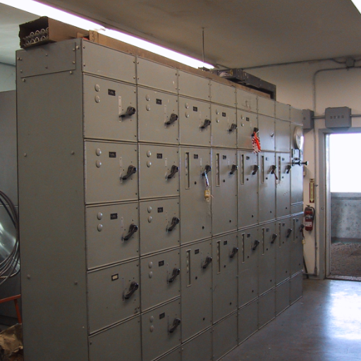
A medium voltage motor control center is a metal-enclosed assembly that groups multiple motor starters, feeders, and auxiliary equipment around a common bus system. Each section contains an isolated power cell for the switching device, a segregated low-voltage control compartment, and internal wireways for power and control cabling.
MV MCC vs LV MCC: Key Differences
The differences between medium voltage and low-voltage motor control centers go beyond the voltage rating.
| Factor | LV MCC (up to 600 V) | MV MCC (1 kV to 15 kV) |
|---|---|---|
| Switching device | Molded-case breaker or contactor | Vacuum contactor or vacuum circuit breaker |
| Bus insulation | Often uninsulated | Frequently insulated or sleeved |
| Arc-resistant option | Available but less common | Standard safety requirement in many industries |
| Walk-in configuration | Common | Not available for arc-resistant designs |
| Section depth | Typically 20 inches | Typically 30 to 36 inches |
| Withdrawable units | Common | Common; required for maintenance access |
| Standards | UL 845, NEMA ICS 2 | UL 347, NEMA ICS 3, IEEE C37.20.7 |
Standard Voltage and Current Ratings
MV MCCs cover a wide range of industrial system voltages:
- Voltage: 2.4 kV, 4.16 kV, 6.6 kV, 7.2 kV, and up to 15 kV
- Main horizontal bus: 800 A, 1,200 A, 2,000 A, 2,500 A, and 3,000 A
- Vertical bus: Typically 400 A or 800 A per section, matching the starter rating
- Starter ratings: 180 A to 1,250 A continuous, depending on voltage class
- Short-circuit withstand: Up to 50 kA rms symmetrical common
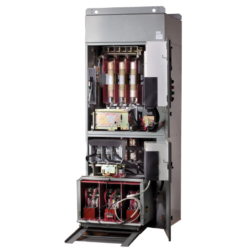
Core Components
Every MV MCC section contains three isolated compartments. The power cell houses the vacuum contactor or circuit breaker. The low-voltage compartment contains control relays, meters, and the control power transformer secondary. The bus compartment contains the horizontal and vertical bus system. Separation between these compartments is essential for arc containment and personnel safety.
Need help selecting the right starter technology for your MCC? See our guide on vacuum contactor motor starters for a complete selection framework.
MV MCC Design: The 7-Step Specification Process
Step 1: Calculate Total Connected Load and Diversified Demand
Start with a motor list showing every motor’s horsepower, voltage, full-load current, and starting method. Sum the full-load currents to get the total connected load. Then apply a diversity factor of 0.7 to 0.9 depending on how many motors run simultaneously. A chemical plant with eight pumps where only six run at once uses a diversity factor of 0.75.
Step 2: Size the Main Horizontal Bus
The main bus ampacity must exceed the diversified demand by a comfortable margin. Industry standard is to add 20 to 30% spare capacity above the diversified load. This accounts for motor contribution during starting and leaves room for future additions without replacing the bus.
Worked example: A 4.16 kV MCC serves eight 500 kW pumps at 84 A full-load current each. Total connected load is 672 A. With a diversity factor of 0.75, diversified demand is 504 A. Adding 25% spare capacity gives 630 A. The next standard bus size is 1,200 A, which provides comfortable margin and allows for four additional pumps without a bus upgrade.
Step 3: Specify Short-Circuit Withstand Rating
The MCC must withstand the maximum prospective fault current at its terminals, including motor contribution. Motor contribution typically adds 3 to 5 times the motor full-load current to the fault. If the available fault current exceeds standard MCC ratings, options include adding feeder impedance, using a higher-rated assembly, or placing the main overcurrent device in a separate enclosure.
Step 4: Select Arc-Resistant or Non-Arc-Resistant Construction
Arc-resistant MCCs are designed following IEEE C37.20. 7 and are rated for Accessibility Type 2B in that they offer protection for operators or maintainers located anywhere around the MCC against arc flash and pressure waves to the same hazard. Specify arc-resistant construction for high fault levels, frequent personnel access, or strict site safety policies. High cost premiums are typically the result of the extra labor necessary for item repairs every 2-5 years, finally drive up to 30-60% but are lower than issues from a single arc flash event that causes process disruption for a day.
Step 5: Choose NEMA Enclosure Type and Environmental Rating
- NEMA 1: General-purpose indoor. Suitable for clean, dry electrical rooms.
- NEMA 12: Dust-tight and drip-proof indoor. The standard choice for industrial environments with dust or occasional moisture.
- NEMA 3R: Outdoor rain-proof. Used when the MCC must be located outside the main building.
For global projects, specify the IEC IP equivalent: NEMA 12 corresponds roughly to IP52, while NEMA 3R corresponds to IP14.
Step 6: Plan Spare Capacity
Spare capacity has two dimensions. First, size the main bus for 20 to 30% more ampacity than the diversified demand. Second, reserve 20 to 25% of the physical sections as empty starter compartments. Empty sections with pre-installed vertical bus allow future starters to be added without shutdown or structural modification.
Step 7: Define Incoming Line Location and Cable Entry
Specify whether the incoming power enters from the top or bottom of the lineup. Bottom entry is common when overhead cable tray space is limited. Top entry simplifies connections from overhead bus duct. The incoming line section should be located at one end of the lineup, with starter sections arranged by process function.
At a data center chiller plant in Germany, the engineering team specified arc-resistant Type 2B MCC for 6.6 kV chillers. They copied a NEMA 12 low-voltage MCC walk-in spec into the medium voltage procurement package. All three bidders returned RFIs asking for clarification. Walk-in is not available for arc-resistant MV MCCs. The spec was rewritten for front-access only with 48-inch aisle clearance. The project lost three weeks to the revision cycle.
Bus System Design and Sizing
Horizontal Bus vs Vertical Bus Ratings
The horizontal bus runs the full length of the MCC and distributes power to each vertical section. The vertical bus drops power from the horizontal bus to each individual starter unit. Horizontal bus ratings are independent of vertical bus ratings. A 2,000 A horizontal bus can feed multiple 400 A vertical sections.
Bus Material and Plating
Main buses are typically silver-plated or tin-plated copper. Silver plating offers lower contact resistance and better oxidation resistance but costs more. Tin plating is acceptable for most indoor industrial applications. A continuous copper ground bus must run the full length of the lineup, sized at not less than 25% of the phase bus ampacity.
Temperature Rise and Heat Rejection
Bus ratings are based on a permissible temperature rise of 50 degrees Celsius over a 40 degree Celsius ambient. The total heat rejection from the bus, contactor coils, and control power transformers must be calculated and addressed in the MCC room HVAC design. A typical mid-sized MV MCC lineup rejects 5 to 10 kW of continuous heat.
Phase Spacing and Clearance Requirements
Adequate phase-to-phase and phase-to-ground clearances are critical for dielectric integrity. For a 7.2 kV system, minimum clearances are roughly 70 to 90 mm. For a 12 kV system, clearances increase to roughly 120 mm. These values must be verified against the basic insulation level (BIL) rating of the assembly.
Mechanical Bracing and Resonance Avoidance
Busbars and supports must withstand the peak asymmetrical fault current, approximately 2.5 times the rms symmetrical current for medium voltage systems. The busbar system must also be checked to ensure its natural resonant frequency does not coincide with operating frequencies or their harmonics.
Arc-Resistant MCC: When and How to Specify
IEEE C37.20.7 Accessibility Types
IEEE C37.20.7 defines how arc-resistant switchgear is tested. Type 2B is the most common rating for MV MCCs. It means that during an internal arcing fault, the enclosure contains the arc effects and safely vents them away from personnel at the front, rear, sides, and low-voltage compartment, even when the LV door is open.
Arc Venting Systems
Arc-resistant MV MCCs use roof-mounted plenums or chimneys to direct arc energy and gases safely away from personnel. Pressure-relief flaps open during a fault to vent the pressure buildup. After the event, the flaps reseal. The plenum adds 12 to 24 inches to the overall height of the MCC.
Arc-Resistant vs Non-Arc-Resistant Cost Impact
| Feature | Non-Arc-Resistant | Arc-Resistant Type 2B |
|---|---|---|
| Cost per section | 15,000to15,000to35,000 | 22,000to22,000to55,000 |
| Height | ~92 inches | ~92 inches plus plenum |
| Personnel protection | Front only | Front, rear, sides, LV compartment |
| Typical applications | Remote, unmanned substations | Process plants with frequent access |
Important Limitation: Walk-In Is Not Available for Arc-Resistant MV
Walk-in aisle configurations, common in low-voltage MCCs, are not standard for arc-resistant medium voltage equipment. The sealed compartments and roof-mounted venting systems required for arc containment are incompatible with aisle-access designs. Specify front-accessible sections with adequate aisle width for withdrawable unit handling.
NEMA Enclosure and Environmental Selection
| NEMA Type | Environment | IP Equivalent | Best For |
|---|---|---|---|
| NEMA 1 | Clean, dry indoor | IP10 | Climate-controlled electrical rooms |
| NEMA 12 | Dust, lint, dripping liquids indoor | IP52 | Most industrial plants, mills, factories |
| NEMA 3R | Outdoor rain, sleet | IP14 | Outdoor substations, remote pump stations |
NEMA 12 is the default specification for indoor MV MCCs in industrial settings. It provides dust-tight seals around doors and panels and protects against dripping liquids. If the MCC room is climate-controlled and impeccably clean, NEMA 1 may be acceptable and costs slightly less. For any outdoor installation, NEMA 3R is mandatory.
MCC Room Design and Layout Considerations
Working Clearances and Arc Flash Boundaries
Minimum working clearances in front of the MCC are typically 3 feet per the National Electrical Code. However, arc flash hazard analysis may require greater distances depending on fault current and clearing time. Always complete an arc flash study before finalizing room layout.
Ventilation and Heat Rejection Calculation
Calculate the total heat rejection from all sources: bus resistive losses, contactor coil holding power, control power transformer losses, and relay power draw. A typical 2,000 A MV MCC with ten 400 A contactor starters may reject 6 to 8 kW continuously. Size the room HVAC for this load plus a 20% margin.
At a steel mill in India, an MV MCC room was designed without heat rejection calculation. Sixteen 400 A contactor starters plus 2,000 A bus produced roughly 8.5 kW of continuous heat. The room HVAC was sized for general ventilation only. Ambient inside the MCC reached 52 degrees Celsius, tripping thermal overloads. A dedicated 12 kW split AC unit had to be retrofitted.
Top Entry vs Bottom Entry Cable Routing
Top entry works well when overhead cable tray or bus duct is available. It keeps power cables above potential floor moisture and simplifies cable routing from overhead transformers. Bottom entry is preferred when overhead space is constrained or when cables enter from underground duct banks. Specify the entry method in the procurement documents to ensure the correct wireway and gland plate configuration.
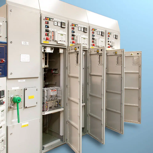
Maintenance Access and Handling Clearance
Withdrawable vacuum contactors and circuit breakers require clearance in front of the section for racking the unit out onto a maintenance cart. A minimum aisle width of 48 inches is recommended for arc-resistant MV MCCs. Heavier units may require an overhead crane or chain hoist. If a crane is not available, specify lifting eyes on the roof and a clear path to the maintenance area.
MV MCC Cost Benchmarks
The following ranges represent 2026 estimates for complete MV MCC sections, including enclosure, bus, starter, fuses, overload relay, control power transformer, and instrumentation.
| Voltage Class | Bus Rating | Non-Arc-Resistant | Arc-Resistant Type 2B |
|---|---|---|---|
| 3.3 to 4.16 kV | 1,200 A | 15,000to15,000to22,000 | 22,000to22,000to32,000 |
| 6.6 to 7.2 kV | 2,000 A | 22,000to22,000to32,000 | 32,000to32,000to48,000 |
| 11 to 12 kV | 2,000 A | 28,000to28,000to38,000 | 42,000to42,000to55,000 |
| 15 kV | 3,000 A | 35,000to35,000to48,000 | 50,000to50,000to70,000 |
What Drives MCC Cost
The three largest cost drivers are bus ampacity, arc-resistant construction, and intelligence features. A 3,000 A bus costs roughly 40% more than a 1,200 A bus in the same voltage class. Arc-resistant construction adds 30 to 60%. Integrated motor protection relays with communications add 10 to 20% per section but reduce external relay panel costs.
Spare Sections: Upfront Cost vs Future Savings
An empty spare section with pre-installed vertical bus costs roughly 40% of a fully equipped starter section. Installing spares during initial construction avoids the much higher cost of shutdown, modification, and recommissioning later. For most projects, the payback period on spare sections is achieved with the first future addition.
Looking for competitive quotations on MV MCC assemblies? Contact our engineering team for project-specific pricing and delivery timelines.
Standards and Compliance
UL 347: Medium Voltage AC Contactors, Controllers, and Control Centers
UL 347 is the primary North American safety standard for MV MCCs up to 7.2 kV. It covers construction, performance, and testing requirements for across-the-line, reduced-voltage, and multi-speed starters. A UL 347 listing is mandatory for installations subject to NEC Article 430 in the United States.
NEMA ICS 3: Medium Voltage Controllers
NEMA ICS 3 defines industrial control systems rated 1,501 to 7,200 V AC. It establishes standard ratings, test procedures, and construction requirements for MV controllers and control centers. NEMA ICS 3 references are common in commercial and industrial specifications.
IEEE C37.20.7: Arc-Resistant Testing
This guide defines the test procedures for evaluating metal-enclosed switchgear for internal arcing faults. Type 2B accessibility, the most common requirement for MV MCCs, is verified by actual fault testing at specified current and duration. Always require test reports from an accredited laboratory.
IEC 62271-200: Metal-Enclosed Switchgear Crosswalk
For international projects outside North America, IEC 62271-200 applies. It covers metal-enclosed switchgear and controlgear for rated voltages above 1 kV. The standard includes requirements for internal arc classification (IAC), which corresponds conceptually to IEEE C37.20.7 accessibility types.
Acceptance Testing and Commissioning
Factory Acceptance Testing Checklist
Before shipment, the manufacturer should perform and document the following tests:
- Dielectric withstand test on all circuits
- Insulation resistance measurement (megger test)
- Contact resistance measurement for each switching device
- Mechanical operation test for each withdrawable unit
- Control circuit functional test
- Protective relay setting verification
- Heater and lighting circuit check
- Dimensional and alignment verification
Site Acceptance Testing Procedures
After installation and before energization, complete these field tests:
- Verify bolted electrical connections torque
- Measure contact resistance and compare to factory values
- Perform insulation resistance test on all circuits
- Verify CT polarity and ratio
- Test protection relay operation and trip circuits
- Verify control power transformer output voltage
- Check space heater operation and thermostat settings
- Confirm arc flash warning labels are posted
Documentation Package Requirements
The supplier should provide certified test reports, single-line diagrams, wiring diagrams, equipment schedules, relay setting sheets, O&M manuals, and spare parts lists. Request electronic copies in both PDF and native CAD formats for future modifications.
Frequently Asked Questions
What does MCC stand for in electrical design?
MCC stands for motor control center. It is an assembly of one or more enclosed sections having a common power bus and containing motor starters, feeders, and auxiliary equipment.
What is the difference between MV and LV MCC?
MV MCC operates at 1 kV to 15 kV and uses vacuum contactors or circuit breakers. LV MCC operates up to 600 V and uses molded-case breakers or magnetic contactors. MV MCCs require greater clearances, arc-resistant construction is more common, and walk-in configurations are not available.
How do I size an MCC main bus?
Sum the full-load currents of all connected motors. Apply a diversity factor of 0.7 to 0.9. Add 20 to 30% spare capacity. Select the next standard bus rating above this calculated value.
What is arc-resistant Type 2B MCC?
Type 2B per IEEE C37.20.7 means the MCC enclosure protects personnel at the front, rear, sides, and low-voltage compartment during an internal arcing fault. It is the most common arc-resistant rating for MV MCCs.
What NEMA enclosure do I need for an MCC?
NEMA 12 is the standard for indoor industrial environments. It is dust-tight and drip-proof. Use NEMA 1 only in clean, climate-controlled rooms. Use NEMA 3R for outdoor installations.
How much does a medium voltage MCC cost?
A single MV MCC section ranges from 15,000forasmallnon−arc−resistant4.16kVunitto15,000forasmallnon−arc−resistant4.16kVunitto70,000 for a large arc-resistant 15 kV unit. Arc-resistant construction adds 30 to 60%.
How much spare capacity should an MCC have?
Size the main bus for 20 to 30% more ampacity than the diversified demand. Reserve 20 to 25% of physical sections as empty starter compartments for future expansion.
What standards apply to MV MCC design?
Primary standards include UL 347, NEMA ICS 3, IEEE C37.20.7, and IEC 62271-200. Additional references include the National Electrical Code for installation requirements and UFC 3-520-01 for military projects.
Conclusion: Specifying the Right MV MCC
The process of specifying a reliable MV MCC takes seven steps: calculate diversified demand, size the main bus with spare capacity, specify adequate short-circuit withstand, select arc-resistant construction when warranted, choose the correct NEMA enclosure, plan physical spares, and define cable entry and incoming line location. Any one of the steps cannot be overlooked: such a mistake caused an Asian EPC engineer to receive buses able to handle steady-state loads but wholly unable to cope with the demand of real-world simultaneous starting and future growth.
Get the bus sizing right, plan for expansion, and verify the arc-resistant rating against your site’s safety policy. The result is an MCC that serves the plant for 20 years without structural modification.
This article is part of our complete medium voltage motor protection and control guide. For related reading, see our guides on vacuum contactor motor starters, motor protection coordination, and medium voltage motor starting methods.
Ready to specify an MV MCC for your next project? Contact our engineering team for application support, specification review, and competitive quotations.
