
Using a cascade topology, multiple single-phase H-bridge cells are employed in series in a cascaded H-bridge inverter to provide smooth AC output, where each cell can provide a positive, negative, or zero voltage to stack the staircase waveform that represents around a sine wave. A great alternative for medium-voltage motor drives above 3.3 kV is the multilevel inverter because the need for high-voltage semiconductors connected in series is eliminated, thus providing a cleaner output with less harmonic distortion compared to the typical two-level designs.
Wang Tao, a power systems engineer working in a cement plant in Jiangsu, was facing a tough decision in November 2024. The issue arose when the factory had to enhance the kiln drive, which, running on 6.6 kV, was even more crucial. The team had been looking at a traditional 2-level IGBT inverter or going with a cascaded H-bridge design–they wanted to go with one that they were quite familiar with under normal circumstances, i.e., a two-level; therefore, the CHB concept was new.
There was nothing but confusion about the 15% upfront cost difference associated with CHB or the advantage of hundreds of tiny switching cells, whereas few or one large switching cells are better than the others. The project went through a 3-week postponement due to these concerns.
The only validation I ever fetched to actually see the difference between some multilevel inverter topologies and to actually understand the superintendent reason why a cascaded H-bridge inverter does make sense for MEDUIM VOLTAGE applications was through this guide. The guide finally starts one off by showing how H-bridge cells work himself, for instance, how a few cells in a series create so many voltage levels while these CHB topologies drive the battery in mining applications, renewable energy and heavy industrial motor control systems. Eventually, the reader will evaluate the CHB with NPC and Flying Capacitor topologies and make a business case that supports why one is chosen over the other in the procurement team.
This is the coverage: H-bridge building blocks and their three switching states, cascading cells that synthesize high-voltage multi-level output, topology comparison, modulation strategies, and relevant industrial applications, and where CHB technology is heading to next.
Key Takeaways
- A cascaded H-bridge inverter connects multiple single-phase H-bridge cells in series to synthesize a multilevel staircase waveform with lower THD than two-level designs.
- Each H-bridge cell produces +Vdc, 0, or -Vdc; n cells in series create 2n+1 output voltage levels per phase.
- CHB inverters need no clamping diodes or flying capacitors, making them the most modular and fault-tolerant multilevel topology.
- Symmetric CHB uses identical DC sources; asymmetric CHB uses binary or trinary ratios to maximize levels with fewer cells.
- Medium voltage motor drives, grid-connected solar PV, and STATCOM systems are the dominant industrial applications for CHB inverters today.
For a deeper technical breakdown of high voltage frequency converter standards, (see our complete guide to medium & high voltage drives.)
What Is a Cascaded H-Bridge Inverter?
Definition and Basic Concept
CHB inverter i.e. cascaded H-Bridge inverter is a type of multilevel inverter that generates AC voltage in relation to the multiple outputs of single-phase H-bridge cells that are connected in series. Each cell works as an independent switching module that has its own DC source.
A CHB inverter produces multiple small voltage levels, which in turn lead to the development of a typical step-like waveform that produces a pure sine wave distortion in comparison to the actual sine wave. This construction minimizes the total harmonic distortion and stress on motor insulation.
How It Fits Within Multilevel Inverter Families
Power electronics recognizes three classical multilevel inverter topologies. The neutral point clamped inverter uses diodes to create intermediate voltage levels. The flying capacitor inverter uses stacked capacitors for the same purpose. The cascaded H-bridge inverter achieves multilevel output through series-connected cells, each with an isolated DC source.
This structural difference gives CHB a unique advantage. It requires no clamping diodes and no flying capacitors. It scales simply by adding more cells in series. For a deeper understanding of how multilevel inverter topologies fit into the complete AC-DC-AC power conversion chain, (read our high voltage frequency converter working principle guide.)
Key Applications
Cascaded H-bridge inverters are deployed wherever medium voltage AC output is required and modularity matters. The primary applications include medium voltage variable frequency drives for pumps, fans, and compressors; grid-connected photovoltaic inverters for utility-scale solar farms; static synchronous compensators for reactive power control; and power electronic transformers for next-generation grid infrastructure.
Low Voltage vs Medium Voltage VFD: Which Should You Choose?
The H-Bridge Building Block, Single Cell Operation
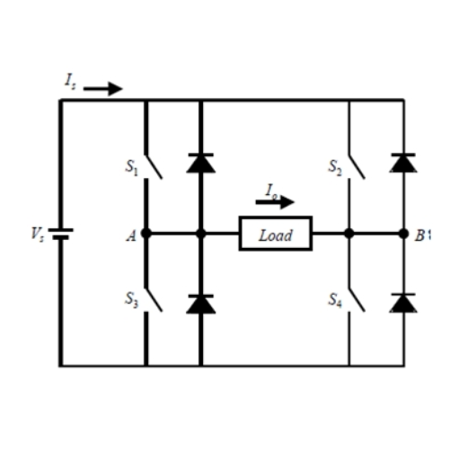
Four-Switch Configuration and Switching States
The fundamental unit of every cascaded H-bridge inverter is the H-bridge cell itself. It consists of four semiconductor switches, typically IGBTs or MOSFETs, arranged in an H-shaped bridge configuration. A DC voltage source connects across the horizontal leg, and the AC output connects across the vertical center.
Each switch pair controls current flow. When the upper-left and lower-right switches conduct, current flows in one direction through the load. When the upper-right and lower-left switches conduct, current flows in the opposite direction.
Output Voltage Levels
An H-bridge cell produces three distinct output states. When the first switch pair is ON, the output is +Vdc. When the second switch pair is ON, the output is -Vdc. When both upper switches or both lower switches are ON, the output is zero.
These three states are the building blocks of every multilevel waveform a CHB inverter creates. No single cell produces a sine wave. The sine wave emerges only when multiple cells combine their outputs in a carefully timed sequence.
Independent DC Source Requirement
Every H-bridge cell in a CHB inverter requires its own isolated DC source. This is a defining characteristic. The DC sources can be batteries, photovoltaic panels, fuel cells, or individual rectifier outputs. In motor drive applications, each cell typically has its own three-phase diode rectifier feeding a DC capacitor.
This independence is why CHB inverters integrate so naturally with renewable energy systems. Each solar panel string can feed its own cell, enabling individual maximum power point tracking.
Cascaded Configuration, Voltage Level Synthesis
Series Connection of H-Bridge Cells
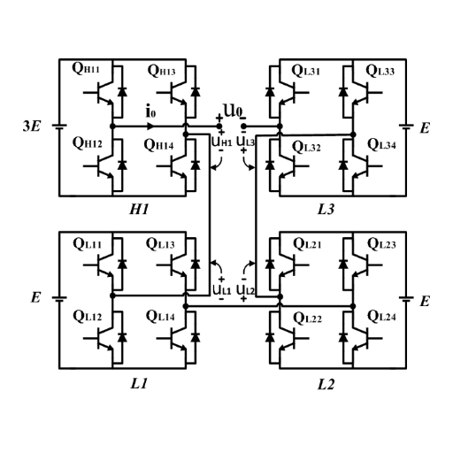
The magic of a cascaded H-bridge inverter happens when multiple H-bridge cells connect in series on their AC output sides. The total phase voltage equals the algebraic sum of each cell’s individual contribution.
If one cell outputs +Vdc, the next outputs 0, and the third outputs +Vdc, the combined output is +2Vdc. By coordinating switching across all cells, the controller can step the output through many discrete voltage levels.
Symmetric vs Asymmetric Configurations
CHB inverters come in two fundamental designs. In a symmetric cascaded H-bridge, every cell uses the same DC voltage. If each cell has a 480 V DC source, then each contributes ±480 V. This is the simplest approach and the most common in industrial motor drives.
In an asymmetric cascaded H-bridge, cells use different DC voltages. A binary ratio uses voltages of Vdc, 2Vdc, 4Vdc, and so on. A trinary ratio uses Vdc, 3Vdc, 9Vdc. Asymmetric designs generate far more voltage levels with fewer cells, but they require more complex control algorithms.
Voltage Level Formula
The relationship between cell count and output levels follows a simple formula. For a symmetric CHB with n cells per phase, the number of voltage levels is 2n + 1.
Two cells create five levels. Three cells create seven levels. Four cells create nine levels.
For an asymmetric binary CHB, the formula expands to 2^(n+1) – 1 levels. Three binary cells produce fifteen levels. This dramatic increase explains why researchers favor asymmetric designs for applications demanding extremely clean output.
Example Designs
A practical 3.3 kV motor drive might use three symmetric cells per phase, each with a 690 V DC bus. This creates a 7-level output. A 6.6 kV drive might use six cells per phase for a 13-level waveform.
In 2023, a steel rolling mill in Hebei commissioned a 10 kV CHB drive with eight cells per phase. Each cell operated at 1,250 V DC. The 17-level output achieved less than 3% THD without any output filter.
Plant engineer Li Ming noted that the most striking difference from their old two-level drive was the absence of motor heating. The clean waveform eliminated the high-frequency losses that had been slowly degrading their 3,500 kW mill motor for years.
CHB vs Other Multilevel Topologies
Neutral Point Clamped (NPC)
The neutral point clamped inverter was the first widely adopted multilevel topology. It uses a single DC bus split into two halves, with clamping diodes creating a third voltage level at the midpoint. NPC inverters are compact and well-proven from 2.3 kV to 4.16 kV.
Above 6.6 kV, NPC designs face serious challenges. The clamping diode count grows exponentially. Capacitor voltage balancing becomes difficult. And a single diode failure can disable the entire phase leg.
Flying Capacitor (FC)
Flying capacitor inverters replace clamping diodes with stacked capacitors. Each additional level requires an additional capacitor. This creates a more modular structure than NPC, but the capacitor count and voltage balancing complexity still limit scalability.
FC inverters find niche applications where fast switching and high dynamics matter. They are rarely used above 6.6 kV in commercial motor drives.
Side-by-Side Comparison
| Feature | NPC | Flying Capacitor | CHB |
|---|---|---|---|
| Clamping components | Diodes | Capacitors | None |
| DC sources | Single | Single | Multiple independent |
| Scalability | Limited | Medium | High |
| Fault tolerance | Low | Medium | High |
| THD at same levels | Moderate | Moderate | Low |
| Best voltage range | 2.3-4.16 kV | 2.3-6.6 kV | 3.3 kV+ |
When to Choose CHB Over NPC or FC
Choose a cascaded H-bridge inverter when your application demands high voltage, modularity, or fault tolerance. CHB is the only topology that scales gracefully to 10 kV and beyond. It is the only topology where a failed cell can be bypassed without stopping the drive. And it is the only topology that directly integrates multiple independent DC sources.
Modulation and Control Strategies
Fundamental Frequency Switching
The simplest control method switches each H-bridge cell at the fundamental output frequency, typically 50 Hz or 60 Hz. The controller calculates the exact switching angles needed to produce the desired staircase waveform with minimum harmonic content.
This approach minimizes switching losses because each semiconductor switches only a few times per cycle. On a 6.6 kV drive with six cells, each IGBT might switch only twice per cycle. The resulting efficiency often exceeds 98%.
Pulse Width Modulation (PWM)
Higher-performance CHB inverters use PWM techniques. Phase-shifted carrier PWM assigns a different carrier waveform to each cell, creating an interleaved switching pattern that cancels harmonics between cells. The effective output switching frequency is much higher than any individual cell’s switching frequency.
This produces cleaner output but increases switching losses. PWM CHB designs typically operate at cell switching frequencies of 500 Hz to 2 kHz.
Selective Harmonic Elimination (SHEPWM)
Selective harmonic elimination is an optimization technique that pre-calculates switching angles to eliminate specific low-order harmonics. For a 7-level CHB, SHEPWM can eliminate the 5th and 7th harmonics entirely. For a 13-level design, it can eliminate harmonics up to the 11th order.
The trade-off is computational complexity. Modern DSP controllers solve these equations in real time using lookup tables and interpolation.
Voltage Balancing Control
In symmetric CHB designs, all cells should share the load equally. In practice, component tolerances, temperature differences, and unequal switching losses create voltage imbalances. Active balancing algorithms adjust switching patterns to keep all DC bus voltages within a narrow band, typically ±3% of nominal.
Advantages and Limitations of CHB Inverters
Modularity and Scalability
The modular nature of CHB inverters is their greatest strength. Need more voltage? Add more cells. Need more power? Add parallel strings of cells. Each cell is identical, which simplifies manufacturing, reduces spare parts inventory, and enables phased commissioning.
A 10 kV drive can be commissioned with six cells per phase and upgraded later to eight cells simply by adding standard modules. No redesign of the power stage is required.
Fault Tolerance and Redundancy
If one H-bridge cell fails in an NPC inverter, the entire drive shuts down. In a CHB inverter, the failed cell can be bypassed. A 7-level drive becomes a 5-level drive.
A 13-level drive becomes an 11-level drive. Production continues at reduced capacity while maintenance schedules the repair.
This capability is why mining and cement operations, where downtime costs tens of thousands of dollars per hour, increasingly specify CHB topologies for critical drives.
Independent DC Sources
The requirement for multiple independent DC sources is both an advantage and a limitation. For renewable energy applications, it enables distributed MPPT and natural battery integration. For standard motor drives, it means each cell needs its own rectifier and transformer winding, increasing front-end complexity and cost.
Component Count and Cost
A 6.6 kV CHB drive with six cells per phase uses 72 IGBTs just for the inverter stage. Add rectifiers, capacitors, gate drivers, and protection circuits, and the component count is substantial. This is why CHB drives typically cost 10-20% more than NPC equivalents at the same power rating.
The business case depends on lifecycle value. Lower harmonic distortion means smaller output filters. Modularity means faster repairs. Fault tolerance means fewer shutdowns.
Voltage Balancing Challenges
Keeping all cell voltages balanced under dynamic load conditions requires sophisticated control. Sudden load changes, regenerative braking, and grid voltage sags can all disturb the balance. Advanced drives use model-predictive control to anticipate and prevent imbalances before they become critical.
Industrial Applications of CHB Inverters
Medium Voltage Motor Drives
Many high-voltage motor control applications, such as the medium-voltage motor, can utilize CHB inverters. For example, electric motors for pumps, fans, compressors, conveyors, and mills operating at 3.3 kV, 4.16 kV, and 6.6 kV make normal use of CHB VFDs.
In 2024, a copper mine in Inner Mongolia installed four 3.3 kV CHB drives on their primary ventilation fans. Each drive had a total of six cells per phase. When a cell failed on account of a gate driver fault during peak summer operation, the drive automatically bypassed it.
The fan ran at 92% of its design capacity. Maintenance replaced the cell the next time the unit was shut down, and production manager Wei Zhao recalcuated that automatic bypass saved approximately $38,000 in lost production revenue.
Grid-Connected Solar PV Systems
Utility-scale solar inverters above 3.3 kV increasingly use CHB topologies. Each PV string connects to its own H-bridge cell. This eliminates string-to-string mismatch losses and enables independent maximum power point tracking for every cell.
A 50 MW solar farm in Qinghai uses CHB inverters with 12 cells per phase. The multilevel output connects directly to the 35 kV collection grid without a step-up transformer. The absence of a 50/60 Hz transformer reduced station losses by 1.2% and cut installation weight by 40 tons.
Static Synchronous Compensators (STATCOM)
STATCOM devices use CHB inverters to inject or absorb reactive power for grid voltage support. The modular design allows precise control of reactive output in small increments. Chinese grid operators have deployed hundreds of CHB-based STATCOMs for voltage stabilization in wind-rich regions.
Power Electronic Transformers
Emerging power electronic transformer designs use CHB cells as the core building block. By cascading cells at both the input and output, these devices replace conventional 50/60 Hz transformers with high-frequency isolation stages. The result is dramatically smaller and lighter equipment for traction and renewable energy applications.
Modern Innovations in CHB Design
SiC MOSFET Integration
Silicon carbide MOSFETs are beginning to replace silicon IGBTs in CHB cells. A SiC-based H-bridge cell can switch at 10 kHz or higher, compared to 1-2 kHz for silicon IGBTs. This enables smaller output filters, faster dynamic response, and higher efficiency.
The efficiency gain matters at scale. Replacing silicon IGBTs with SiC MOSFETs in a 10 MW CHB drive can improve efficiency by 1-2%. Over 8,000 operating hours per year, that is 800,000 to 1,600,000 kWh of saved energy.
Reduced Switch-Count Topologies
Researchers are developing modified CHB topologies that reduce semiconductor count. Cross-switched cell designs and T-type H-bridge variants use fewer switches per cell while maintaining the same output levels. For a 7-level design, these topologies can cut switch count by 25-30%, directly reducing cost and conduction losses.
Hybrid CHB-NPC Configurations
Some manufacturers combine CHB and NPC principles in hybrid designs. An NPC front-end creates multiple DC levels, and CHB cells process each level. This approach achieves very high level counts with moderate component counts, though at the cost of reduced modularity.
Digital Control and Predictive Algorithms
Modern CHB drives use field-programmable gate arrays (FPGAs) and high-speed digital signal processors to execute model-predictive control. Instead of reacting to voltage imbalances after they occur, predictive algorithms forecast load changes and pre-adjust switching patterns. This reduces voltage ripple by 40-60% compared to traditional PI controllers.
Conclusion
The cascaded H-bridge inverter is not simply a variation of multilevel inverter design, but it is yet another, fundamentally new approach to high-voltage power conversion. CHB topology brings about modularity, fault tolerance, and the output quality that monolithic design cannot.
The principle of operation is simple to comprehend. Each H-bridge cell contributes either +Vdc, -Vdc, or just 0. These contributions are then added together in the series connection. Careful switching states build a staircase waveform; with the increase in the number of cells, this waveform can approach a pure sine wave.
In view of medium voltage drive performance, the comparisons on CHB and all the other systems depend on the requirements of the respective end-use application. If high reliability, clean output and integration with multiple DC sources are major demand factors of your particular installation, then the Cascaded H-Bridge definitely becomes the eventual choice. However, should the cost be of prime dominance coupled with a lower-risk application, NPC or two-level options could be a way forward.
If you are struggling with deciding on the cascaded H-bridge inverter, cell count optimization, and custom configuration for your medium voltage application, please feel free to reach out for our engineering team. We design and manufacture modular multilevel powers conversion systems: 3.3kV-11kV. CHB, NPC, and hybrid topologies are thus custom-tailored to the mining, green energy, and heavy industrial sectors, never leaving the global stage, of course.
For a thorough technical breakdown of medium voltage drive power quality challenges, encompassing harmonic mitigation techniques and relevant industry standards, see our comprehensive power quality guide.
Frequently Asked Questions
How does a cascaded H-bridge inverter work?
A cascaded H-bridge inverter works by connecting multiple single-phase H-bridge cells in series on the AC output side. Each cell switches its independent DC source to produce +Vdc, -Vdc, or zero. The series connection sums these individual outputs into a multilevel staircase waveform.
What is the difference between symmetric and asymmetric cascaded H-bridge inverters?
A symmetric CHB uses identical DC voltage sources for all cells. An asymmetric CHB uses different DC voltages, typically in binary or trinary ratios. Asymmetric designs produce more voltage levels with fewer cells but require more complex control.
How many voltage levels does a cascaded H-bridge inverter produce?
A symmetric CHB with n cells per phase produces 2n+1 voltage levels. Two cells produce 5 levels. Three cells produce 7 levels. Six cells produce 13 levels.
An asymmetric binary CHB with n cells produces 2^(n+1)-1 levels.
Why are cascaded H-bridge inverters preferred for medium voltage drives?
CHB inverters scale to high voltage by adding identical cells rather than relying on series-connected high-voltage semiconductors. They offer fault tolerance, modularity, and clean output waveforms. Failed cells can be bypassed without drive shutdown.
What are the main applications of cascaded H-bridge inverters?
The dominant applications are medium voltage motor drives for pumps, fans, and compressors; grid-connected photovoltaic inverters; static synchronous compensators for grid voltage support; and emerging power electronic transformer designs.
