
A solid state frequency converter is an electronic power conversion system that transforms AC power at one frequency into AC power at a different frequency through an intermediate DC stage, using semiconductor devices with no moving mechanical parts. The conversion follows an AC-DC-AC architecture: rectification, DC link filtering, and IGBT-based PWM inversion.
When procurement engineer David Chen reviewed three quotes for a 90 kVA aircraft ground power unit, he noticed each supplier listed different rectifier types, IGBT modules, and PWM carrier frequencies. Without understanding what these specifications meant, he could not determine which quote offered genuine engineering value and which one cut corners on components. This guide solves that problem by breaking down every stage of a solid state frequency converter so buyers know what to specify and what to verify.
Key Takeaways
- A solid state frequency converter uses AC-DC-AC architecture with four stages: rectification, DC link filtering, IGBT-based PWM inversion, and output filtering.
- Rectifier type matters: diode bridges are simple and reliable, while active front-ends enable bidirectional power flow and regenerative braking.
- IGBT switching at 2-16 kHz carrier frequency synthesizes the output waveform; higher carrier frequencies improve waveform quality but increase switching losses.
- DC link capacitor health determines converter lifespan; electrolytic capacitors typically last 10-15 years and degrade faster at elevated temperatures.
- Understanding component specifications helps buyers evaluate quotes, avoid undersized designs, and specify the right converter for their application.
The AC-DC-AC Architecture Overview
Every solid state frequency converter, whether producing 50Hz for industrial testing or 400Hz for aircraft ground power, follows the same fundamental signal path. Input AC power enters a rectifier stage that converts it to DC. A DC link circuit smooths and stores this DC voltage. An inverter stage then switches the DC at high frequency to reconstruct AC output at the desired frequency. Finally, an output filter removes switching noise before the power reaches the load.
This architecture replaces the motor-generator sets used in rotary frequency converters. Instead of spinning mechanical components, all conversion happens through semiconductor switching. The absence of bearings, brushes, and couplings fundamentally changes the maintenance profile and enables precise digital control over output parameters.
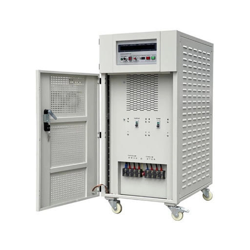
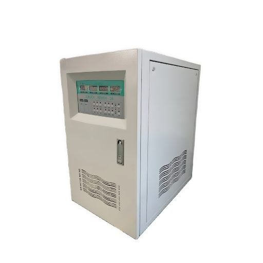
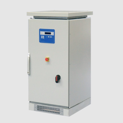
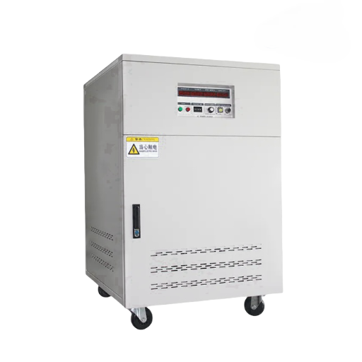
At Shandong Electric, we design solid state converters across power ratings from 1 kVA laboratory units to 2,000+ kVA industrial systems. The same AC-DC-AC core scales across this entire range, though component selection and control strategies vary significantly by application.
Want the broader picture? Our complete static frequency converter guide covers applications, selection criteria, and total cost of ownership across aviation, industrial, and defense sectors.
Stage 1: Rectification
The rectifier is the first active stage in a solid state frequency converter. Its job is to convert the incoming AC power, typically 380V/400V at 50Hz or 480V at 60Hz, into pulsating DC voltage. Three common rectifier technologies exist, and the choice between them affects cost, efficiency, harmonic generation, and capability.
Diode Bridge Rectifiers
A six-diode full-bridge rectifier is the simplest and most common approach. The diodes conduct naturally as the AC voltage cycles, producing a six-pulse DC output with ripple at 300Hz for 50Hz input or 360Hz for 60Hz input.
The advantages are clear: no control circuitry needed for the rectifier, extremely high reliability, and low cost. The output DC voltage is fixed by the input AC amplitude. For a 400V AC input, the DC bus sits at approximately 565V DC (400V multiplied by the square root of 2).
The limitation is equally clear. A diode bridge cannot control output voltage, cannot return power to the grid, and generates input current harmonics that may require external filtering to meet IEEE 519 or IEC 61000 limits. For many applications, these limitations are acceptable. For others, they are deal-breakers.
Thyristor (SCR) Rectifiers
Thyristors, also called silicon controlled rectifiers (SCRs), add phase-control capability. By delaying the turn-on point within each AC cycle, the rectifier can adjust the average DC output voltage. This enables soft-start of the DC bus and controlled charging of capacitors.
Thyristor rectifiers also handle reverse power flow in regenerative applications, such as when a descending crane or decelerating flywheel returns energy to the DC bus. However, phase-controlled rectification produces more harmonic distortion and a lower power factor than diode bridges. Modern designs increasingly prefer active front-ends for applications requiring these capabilities.
Active Front-End (AFE) Rectifiers
An active front-end replaces the diodes or thyristors with IGBT switches operating in rectifier mode. This approach offers three significant advantages.
First, active power factor correction brings the input power factor near unity, reducing reactive power draw and utility penalties. Second, bidirectional power flow enables regenerative braking without additional hardware. Third, the controlled DC bus voltage remains stable regardless of input fluctuations, which improves inverter performance.
The trade-off is cost and complexity. AFE rectifiers require more IGBTs, more control circuitry, and more sophisticated firmware. For standard 50/60Hz to 400Hz conversion in aviation ground power, a well-designed diode bridge with input filtering is usually sufficient. For industrial test systems with dynamic loads or strict harmonic limits, the AFE investment pays dividends.
| Rectifier Type | Cost | Input Harmonics | Bidirectional Power | Best For |
|---|---|---|---|---|
| Diode Bridge | Low | Moderate | No | Standard aviation and industrial conversion |
| Thyristor (SCR) | Medium | High | Yes | Regenerative, very high power |
| Active Front-End | High | Very Low | Yes | Dynamic loads, strict harmonic limits |
Stage 2: The DC Link
The DC link bridges the rectifier and inverter. Its primary functions are energy storage, voltage smoothing, and galvanic isolation between input and output stages.
DC Bus Capacitor Function
Electrolytic capacitors dominate DC link design for solid state frequency converters up to approximately 500 kVA. These capacitors absorb the ripple current from the rectifier and supply transient current to the inverter during load steps. Without adequate capacitance, the DC bus voltage sags during inverter switching, degrading output waveform quality.
Capacitor selection involves three parameters: capacitance value, voltage rating, and ripple current rating. The capacitance must be large enough to keep voltage ripple within acceptable limits, typically 5-10% of nominal DC bus voltage. The voltage rating must exceed the maximum DC bus voltage with safety margin, usually 1.2x to 1.5x. The ripple current rating must exceed the actual ripple current generated by the inverter switching.
DC Link Inductors
Many designs include a DC link inductor between the rectifier and capacitor bank. The inductor serves two purposes. It limits inrush current when the converter is first energized, protecting the rectifier diodes and capacitors. It also reduces the ripple current seen by the capacitors, extending their operational life.
DC Link Health and Aging
Electrolytic capacitors are the most common failure mode in solid state frequency converters. Their electrolyte evaporates over time, causing equivalent series resistance (ESR) to increase and capacitance to decrease. The Arrhenius equation governs capacitor aging: life approximately halves for every 10 degrees Celsius increase in core temperature above rated.
This means a capacitor rated for 10,000 hours at 105 degrees Celsius may last only 2,500 hours if operated continuously at 125 degrees Celsius. In practice, well-designed converters with adequate cooling achieve 10-15 year capacitor life. Converters in poorly ventilated enclosures or hot climates may need capacitor replacement after 7-8 years.
At a converter service center in Dubai, technicians tracked capacitor failures across forty units installed in outdoor electrical shelters. Units with ambient temperatures below 40 degrees Celsius averaged 14 years before capacitor replacement. Units in shelters exceeding 55 degrees Celsius averaged only 6 years. The difference was not manufacturing quality. It was thermal management.
Stage 3: Inversion
The inverter stage is where frequency conversion actually happens. It takes the stable DC voltage from the DC link and reconstructs AC power at the desired output frequency using high-speed semiconductor switches.
IGBT Basics for Frequency Converters
Insulated Gate Bipolar Transistors (IGBTs) are the standard switching device in modern solid state frequency converters. An IGBT combines the gate control characteristics of a MOSFET with the high-current conduction capability of a bipolar transistor.
When a positive voltage is applied between gate and emitter, a conductive channel forms. When the gate voltage is removed, the device turns off. This gate-controlled behavior enables precise switching timing, which is essential for PWM operation.
IGBT modules for frequency converters typically have voltage ratings of 600V, 1200V, or 1700V. A 400V AC input with diode rectification produces approximately 565V DC, so 1200V IGBTs provide comfortable safety margin. Aviation 400Hz converters with 115V/200V output may use 600V modules in the inverter stage.
Each IGBT in the inverter bridge includes an anti-parallel freewheeling diode. When an inductive load, such as a motor or transformer, demands continuous current during the switch-off interval, this diode provides a path for the inductive energy rather than allowing destructive voltage spikes.
PWM Switching Fundamentals
Pulse Width Modulation is the technique used to synthesize a sinusoidal output from the fixed DC bus voltage. The IGBT switches connect the DC bus positive, negative, or neutral to each output phase in rapid pulses. By varying the width of these pulses according to a reference sine wave, the average output voltage over each microsecond follows the desired sinusoidal shape.
The switching frequency, also called carrier frequency, typically ranges from 2 kHz to 16 kHz for industrial solid state frequency converters. Higher carrier frequencies produce smoother output waveforms with lower audible noise, but they also increase switching losses in the IGBTs and generate more electromagnetic interference.
For a 400Hz aviation ground power unit, carrier frequencies of 8-12 kHz are common. This provides a 20:1 to 30:1 ratio between carrier and output frequency, which yields clean waveform reconstruction. For 50Hz or 60Hz industrial outputs, 3-6 kHz may be sufficient.
SPWM vs SVPWM
Two PWM techniques dominate solid state frequency converter design.
Sinusoidal Pulse Width Modulation (SPWM) compares a sinusoidal reference wave against a triangular carrier wave. The intersection points determine switching instants. SPWM is straightforward to implement and produces good waveform quality.
Space Vector Pulse Width Modulation (SVPWM) treats the three-phase inverter as a single vector in a two-dimensional plane. By selecting optimal switch states, SVPWM achieves approximately 15% better DC bus voltage utilization than SPWM. This means a converter using SVPWM can produce about 15% more output voltage from the same DC bus, which translates to either higher output capability or lower IGBT current stress.
Most modern solid state frequency converters use SVPWM for this efficiency advantage, though SPWM remains common in simpler designs.
Three-Phase Inverter Bridge
A three-phase inverter uses six IGBTs arranged in three half-bridge legs. Each leg has a high-side switch connected to the positive DC bus and a low-side switch connected to the negative DC bus. The output phase connects to the midpoint between them.
The three legs operate with 120-degree phase displacement. At any instant, one leg may be switching high while another switches low, with the third in transition. Dead-time, a brief interval where both switches in a leg are off, prevents shoot-through short circuits across the DC bus.
Stage 4: Output Filtering
The inverter output contains high-frequency switching components at the carrier frequency and its harmonics. These must be removed before the power reaches the load.
LC Filter Design
An LC filter consists of a series inductor and shunt capacitor for each output phase. The inductor blocks high-frequency current while passing the fundamental frequency. The capacitor shunts high-frequency voltage to neutral.
Filter cutoff frequency is typically set between 1/10 and 1/5 of the carrier frequency. For a converter with 8 kHz carrier frequency, a cutoff of 1-2 kHz attenuates switching components while passing 400Hz or 50/60Hz fundamental output cleanly.
The trade-off is component size. Lower cutoff frequency requires larger inductors and capacitors. Aviation converters where weight matters may accept slightly higher output THD in exchange for smaller filters. Industrial converters where size is less critical can use more aggressive filtering.
Isolation Transformer
Many solid state frequency converters include an output isolation transformer. This provides galvanic separation between input and output grounds, which prevents ground loop currents and protects downstream equipment from input-side disturbances. The transformer also provides additional voltage transformation if the inverter output does not match the required load voltage directly.
Filter Impact on Performance
A well-designed output filter reduces Total Harmonic Distortion from 5-10% at the inverter terminals to under 1-3% at the load connection point. For aircraft ground power, MIL-STD-704F specifies THD below 5%, with many airlines requiring under 3%. For sensitive industrial test equipment, under 2% may be necessary.
Voltage-to-Frequency Ratio (V/Hz) Control
For motor loads, maintaining constant magnetic flux requires that voltage scale proportionally with frequency. If a motor designed for 400V at 50Hz is operated at 60Hz without voltage adjustment, the flux drops and torque suffers. If voltage is raised without increasing frequency, the magnetic core saturates and overheats.
The relationship is straightforward:
V_out = V_rated x (f_out / f_rated)
A solid state frequency converter with V/Hz control automatically adjusts output voltage as frequency changes. Digital controllers implement this by scaling the PWM modulation index in proportion to the commanded frequency. Modern controllers can also apply boost voltage at low frequencies to compensate for resistive voltage drop in motor windings.
Digital Control and Monitoring Systems
The control system is the brain of a solid state frequency converter. It determines switching timing, regulates output voltage and frequency, and protects the hardware from fault conditions.
DSP and Microcontroller Architecture
Modern converters use Digital Signal Processors (DSPs) or high-performance microcontrollers to execute control algorithms. These processors sample output voltage and current at rates of 10-20 kHz, execute control loops every 50-100 microseconds, and update PWM duty cycles in real time.
Dual-loop control is standard practice. An inner current loop responds rapidly to load transients, limiting overcurrent within microseconds. An outer voltage loop adjusts the current reference to maintain precise output voltage regulation, typically within plus or minus 1%.
Protection Algorithms
The digital controller monitors multiple fault conditions simultaneously. Overcurrent protection acts cycle-by-cycle, turning off IGBTs before damage occurs. Overvoltage protection clamps or shuts down when DC bus voltage exceeds safe limits. Overtemperature protection uses NTC thermistors embedded in the IGBT modules to monitor junction temperature. Phase loss detection identifies when an output phase becomes disconnected and responds appropriately.
Remote Monitoring Interface
Most industrial and aviation solid state frequency converters now include communication interfaces for remote monitoring and control. RS-485 with Modbus protocol is common in industrial settings. Ethernet with TCP/IP enables integration with building management systems. CAN bus appears in military and aerospace applications.
These interfaces allow operators to monitor voltage, current, temperature, and fault status from a central location. Predictive maintenance algorithms can track capacitor ESR trends, IGBT thermal cycling, and fan operating hours to schedule maintenance before failures occur.
Converter Topologies: Two-Level, Three-Level, and Beyond
Not all solid state frequency converters use the same inverter architecture. Three topologies dominate different power ranges and applications.
Two-Level Inverter
The standard six-switch bridge produces output voltage at two levels: positive DC bus and negative DC bus. This is the simplest, most proven, and lowest-cost topology. It dominates applications up to approximately 500 kVA.
The limitation is high dv/dt, the rate of voltage change during switching. Fast voltage transitions can cause motor bearing currents, cable reflections, and electromagnetic interference. Output filters mitigate these effects but add cost and size.
Three-Level NPC Inverter
Neutral Point Clamped inverters use twelve switches with a DC bus midpoint connection. They produce output voltage at three levels: positive, zero, and negative. This reduces dv/dt by half compared to two-level designs, improves waveform quality, and lowers harmonic output.
The trade-off is complexity. Three-level inverters require capacitor voltage balancing to maintain equal DC bus halves, more gate drive circuitry, and more sophisticated control algorithms. They are preferred for medium-voltage applications and installations where output power quality is critical.
Multilevel Cascaded H-Bridge
For very high power applications, modular multilevel converters connect multiple H-bridge cells in series. Each cell has its own isolated DC source. The series stack produces output voltage with many discrete levels, yielding near-sinusoidal output with minimal filtering.
This topology scales to megawatt power levels for utility grid coupling and large industrial drives. It is rarely used in standard aviation or industrial frequency conversion below 1 MVA.
| Topology | Switches | Output Levels | Best For | Complexity |
|---|---|---|---|---|
| Two-Level | 6 | 2 | Up to 500 kVA, standard applications | Low |
| Three-Level NPC | 12 | 3 | Medium voltage, high power quality | Medium |
| Multilevel H-Bridge | 4N | N+1 | Very high power, utility scale | High |
Specifications Buyers Should Request
When evaluating quotes for a solid state frequency converter, these specifications reveal genuine engineering quality versus corner-cutting.
Rectifier: Specify type (diode, thyristor, or AFE) and input current THD at full load. For standard applications, a diode bridge with THD under 30% is acceptable. For strict grid codes, require AFE with THD under 5%.
DC Link: Request capacitor voltage rating, capacitance value, and ripple current rating. Verify these are adequate for your application’s duty cycle and ambient temperature.
IGBT Module: Note voltage rating, current rating, and manufacturer. Major brands include Infineon, Fuji Electric, and Mitsubishi. Specify minimum carrier frequency for your application: 3-4 kHz minimum for 50/60Hz output, 8-12 kHz for 400Hz aviation.
Output Performance: Require THD specification at rated load and at no-load. No-load THD often exceeds loaded THD because the filter is optimized for rated current.
Efficiency: Request efficiency at 25%, 50%, 75%, and 100% load. Many converters advertise peak efficiency at 75-80% load, but your application may operate at lighter loads where efficiency drops.
Environmental: Specify cooling method (air or liquid), maximum ambient temperature, and IP rating. A converter rated for 40 degrees Celsius will derate significantly at 50 degrees Celsius unless specifically designed for high temperature.
Control and Monitoring: List required communication protocols, protection features, and remote monitoring capabilities.
Conclusion
A solid state frequency converter is not a black box. It is a carefully engineered chain of stages, each with specific component choices that affect performance, reliability, and cost. The rectifier determines input power quality and bidirectional capability. The DC link capacitors set the operational lifespan. The IGBT inverter and PWM control define output waveform quality. The output filter protects downstream equipment from switching noise.
Understanding these stages helps buyers move beyond comparing headline power ratings. It enables informed evaluation of rectifier type, capacitor specifications, IGBT ratings, and control features. It reveals where one supplier invested in quality and where another cut costs.
At Shandong Electric, we design and manufacture solid state frequency converters with full transparency on component selection and specifications. Whether you need a 400Hz aviation ground power unit, a 50/60Hz industrial test system, or a custom frequency conversion solution, our engineering team can walk you through the component choices that match your application.
Ready to specify your solid state frequency converter? Contact our engineering team for component-level specification support, or explore our 400Hz frequency converter range for aviation applications.
