
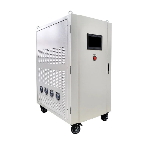
A static frequency converter is a solid-state electronic power conversion system that changes AC power from one frequency to another through an intermediate DC stage, with no rotating mechanical parts. It is the core technology behind aircraft ground power units, industrial test systems, railway grid coupling, and military base power supplies worldwide.
If you are sizing a 400Hz GPU for an airport gate, testing export equipment on a mismatched grid, or replacing an aging rotary motor-generator set, the same fundamental question applies: how do you specify a static frequency converter that delivers stable output, meets your standards, and minimizes total cost of ownership? This guide answers that question with engineering-level depth.
Key Takeaways
- A static frequency converter uses AC-DC-AC conversion through IGBT-based PWM inversion to produce precise output frequency with no moving parts.
- For most applications below 2,000 kVA, static converters outperform rotary sets in efficiency, maintenance, noise, and footprint.
- 400Hz aircraft ground power is the largest commercial application, requiring tight voltage and frequency tolerances per ISO 6858 and MIL-STD-704F.
- Selecting the right unit requires load type analysis, input/output voltage matching, harmonic compliance, and cooling assessment.
- Over a 10-year lifecycle, a static converter typically saves 30-50% in maintenance and energy costs compared to an equivalent rotary set.
What Is a Static Frequency Converter?
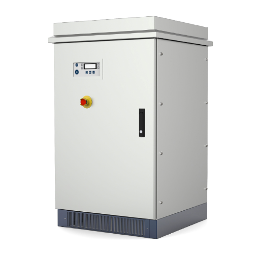
A static frequency converter is an electronic power conditioning system that converts fixed-frequency AC input power into AC output power at a different frequency and often a different voltage. Unlike rotary frequency converters, which use a motor-generator set with spinning mechanical components, a static frequency converter performs this conversion entirely through semiconductor switching.
The term “static” refers to the absence of moving parts. There are no bearings to lubricate, no brushes to replace, and no alignment to maintain. This design choice fundamentally changes the maintenance profile, noise signature, and physical footprint of the equipment.
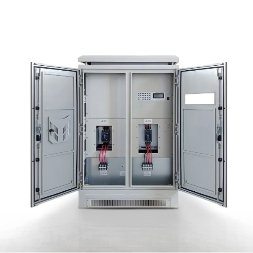
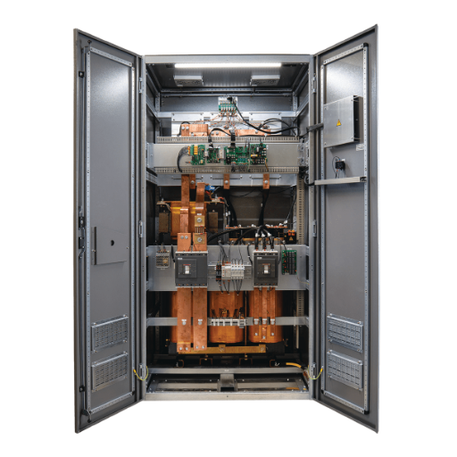
At its core, every static frequency converter follows an AC-DC-AC architecture. The incoming AC power is first rectified to DC, then filtered and stored in a DC link, and finally inverted back to AC at the desired output frequency using high-speed semiconductor switches. The result is a clean, stable output waveform that can be precisely controlled.
Static frequency converters are manufactured in power ratings from approximately 1 kVA for laboratory test benches up to 2,000+ kVA for industrial and grid-coupling applications. At Shandong Electric, we design and build static converters across this entire range, with particular focus on 400Hz aviation ground power and industrial 50/60 Hz conversion systems.
Want to understand the internal electronics in more detail? Our deep-dive article on solid state frequency converter working principle breaks down the rectifier, DC link, and inverter stages component by component.
How Static Frequency Converters Work
Understanding the working principle of a static frequency converter helps buyers evaluate specifications, compare quotes, and troubleshoot issues in the field. The process follows four distinct stages.
Stage 1: Rectification
The input AC power, typically 380V/400V at 50Hz or 480V at 60Hz, enters a rectifier stage. This stage converts the alternating current into pulsating direct current. Two common rectifier types exist:
- Diode bridge rectifiers: Simple, reliable, and cost-effective for applications where power flows in one direction only.
- Active front-end (AFE) rectifiers: Use IGBT switches to enable bidirectional power flow, regenerative braking, and active power factor correction. AFE rectifiers reduce input current harmonics but add cost and complexity.
For most industrial and aviation static frequency converters, a well-designed diode bridge with input filtering is sufficient. AFE becomes valuable when the converter must return energy to the grid or when strict harmonic limits apply.
Stage 2: DC Link Filtering
The rectified DC voltage contains ripple at twice the input frequency (100Hz for 50Hz input, 120Hz for 60Hz input). A DC link circuit smooths this ripple using capacitors and, in some designs, inductors. The DC link serves two critical functions:
- Energy storage: It buffers energy between the input and output stages, allowing the inverter to draw consistent power even during load transients.
- Galvanic isolation: When combined with an isolation transformer, it separates the input and output electrically, protecting against ground loops and fault propagation.
The DC bus voltage must be maintained above a minimum threshold. For a 400V AC input, the rectified DC bus sits at approximately 565V DC (400V x sqrt(2)). The inverter then uses this DC voltage as its source.
Stage 3: Inversion
This is where the frequency conversion happens. An inverter stage uses insulated-gate bipolar transistors (IGBTs) to switch the DC bus voltage on and off at high frequency, typically 2-16 kHz. By varying the pulse width and timing, the inverter synthesizes an AC output waveform at the desired frequency.
The most common control technique is Sinusoidal Pulse Width Modulation (SPWM). In SPWM, a high-frequency carrier wave is compared against a reference sine wave. The intersection points determine the switching instants. When filtered, the resulting output closely approximates a pure sine wave.
For three-phase output, three inverter legs operate with 120-degree phase displacement. The switching pattern for each leg is independent, allowing precise control of voltage, frequency, and phase balance.
Stage 4: Output Filtering and Isolation
The inverter output contains high-frequency switching components that must be removed before reaching the load. An output LC filter attenuates these components, leaving a clean sinusoidal waveform.
An output isolation transformer provides three benefits:
- Galvanic isolation: Protects the load from input-side disturbances.
- Voltage transformation: Steps the inverter output up or down to match load requirements.
- Harmonic buffering: The transformer impedance helps filter residual high-frequency content.
Voltage-to-Frequency Ratio Control
For motor loads, the voltage must scale proportionally with frequency to maintain constant magnetic flux. If a motor designed for 400V/50Hz is run at 60Hz without voltage adjustment, the flux drops and torque suffers. If voltage is increased without raising frequency, the motor saturates and overheats.
The relationship is:
V_out ≈ V_in × (f_out / f_in)
A static frequency converter with V/Hz control automatically maintains this ratio, ensuring motor compatibility across the operating range.
Digital Closed-Loop Control
Modern static frequency converters use digital signal processors (DSPs) or microcontrollers to implement closed-loop control. The controller continuously monitors output voltage, current, frequency, and temperature. If the load changes suddenly, such as when an aircraft air conditioning system cycles on, the controller adjusts the inverter switching within milliseconds to maintain stable output.
This digital architecture also enables remote monitoring, predictive maintenance alerts, and programmable operating sequences. Many converters now include Ethernet, RS-485, or CAN bus interfaces for integration with building management or SCADA systems.
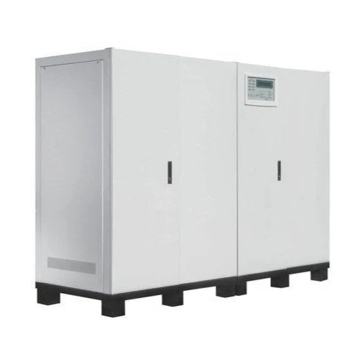
Static vs Rotary Frequency Converters
The choice between static and rotary frequency converter technology is one of the first decisions buyers face. Both convert power from one frequency to another, but they do so through fundamentally different means.
How Each Technology Works
A rotary frequency converter consists of an electric motor mechanically coupled to a generator. The motor runs at the input frequency (say, 50Hz) and spins the generator, which is wound to produce the output frequency (say, 60Hz or 400Hz). The mechanical coupling can be direct (common shaft) or through a gearbox or belt.
A static frequency converter, as described above, uses all-electronic conversion with no moving parts.
Side-by-Side Comparison
| Criteria | Static Converter | Rotary Converter |
|---|---|---|
| Moving parts | None | Motor, generator, bearings, coupling |
| Maintenance | Minimal (fans, filters, capacitors) | Regular (bearings, brushes, alignment) |
| Efficiency | 93-97% at rated load | 80-92% depending on design |
| Noise level | Very low (fan noise only) | High (mechanical + fan) |
| Output frequency | Programmable and variable | Typically fixed by winding design |
| Size and weight | Compact, high power density | Large and heavy |
| Surge capacity | Limited by semiconductor ratings | High (motor inertia provides ride-through) |
| Power range | 1 kVA to 2,000+ kVA | 10 kVA to 5,000+ kVA historically |
| Initial cost | Lower per kVA in most ranges | Higher, especially with maintenance infrastructure |
| Harmonic output | Lower with good filter design | Naturally sinusoidal (no switching) |
| Environmental | No oil, no brushes, no wear debris | May require lubrication and brush replacement |
When Static Wins
For most new installations in 2026, the static frequency converter is the preferred choice. The advantages are clear:
- Lower total cost of ownership: Eliminating bearing replacements, brush changes, and alignment checks saves thousands of dollars annually.
- Smaller footprint: A 100 kVA static converter typically occupies 40-60% less floor space than an equivalent rotary set.
- Quieter operation: Critical for airport gates adjacent to terminals, military bases near barracks, and factory floors.
- Precise control: Digital frequency programming allows test systems to sweep frequencies, simulate grid disturbances, and match exact customer requirements.
- Higher efficiency: Less energy lost as heat means lower operating costs and reduced cooling requirements.
When Rotary Still Makes Sense
Despite the advantages of static technology, rotary converters retain value in specific scenarios:
- Very heavy surge loads: When a load draws massive inrush current, such as a large motor direct-on-line start, the inertia of a spinning motor-generator can absorb the transient without tripping. Static converters must be oversized for surge capacity.
- Extremely dirty input grids: In locations with severe voltage distortion, sags, or interruptions, a rotary converter’s mechanical inertia can ride through brief disturbances that would trip a static unit.
- Very high power, legacy infrastructure: In some utility-scale installations above 5 MVA, existing rotary sets may remain cost-effective compared to massive static installations.
- Clean sinusoidal output requirement: For certain sensitive test applications, the naturally smooth output of a generator may be preferable to a filtered PWM waveform.
Need a deeper comparison? Read our dedicated analysis of static vs rotary frequency converters with a 10-year TCO worked example.
A Real-World Decision
When the engineering team at a Southeast Asian airport evaluated replacement options for their aging 75 kVA rotary GPUs, the numbers told a clear story. The rotary sets required bearing replacement every 18 months at $2,800 per unit, plus annual brush inspection and alignment. Over five years, maintenance alone costs 2,800 per unit, plus annual brush inspection and alignment. Over five years, maintenance alone costs 22,000 per unit. The replacement static frequency converters had a 30% smaller footprint, eliminated all mechanical maintenance, and improved efficiency from 84% to 94%. The payback period on the upgrade was under three years.
Applications and Industries
Static frequency converters serve a diverse range of industries. Understanding how the technology applies to your sector helps clarify specifications and selection criteria.
Aviation and Aircraft Ground Power
The largest commercial application for static frequency converters is aircraft ground power. Commercial and military aircraft universally operate on 115V/200V, 400Hz, three-phase AC power. Airport utility grids supply 50Hz or 60Hz. The gap is bridged by 400Hz static frequency converters, commonly called Ground Power Units (GPUs).
Why 400Hz? Higher frequency allows onboard transformers, motors, and generators to be significantly smaller and lighter. At 400Hz, a transformer can be roughly 1/8 the weight of its 50Hz equivalent for the same power rating. For an aircraft where every kilogram affects fuel burn, this weight reduction is essential.
Three types of ground power systems exist:
- Fixed centralized systems: Large converters located in electrical rooms distribute 400Hz power through underground cables to multiple gates. Economical for airports with high gate density.
- Point-of-use converters: Individual static converters mounted on jet bridges or installed in pits at each gate. Reduces cable losses and improves reliability through decentralization.
- Mobile GPUs: Self-contained units on wheeled carts or towable trailers. Used for remote stands, maintenance hangars, and military forward operating bases.
Power quality requirements for aviation are strict. Typical specifications include:
- Voltage: 115V phase-to-neutral / 200V line-to-line (adjustable ±20%)
- Frequency: 400Hz ±0.01% (±0.04Hz)
- Voltage regulation: ±1% under steady-state conditions
- THD: <3%, with <1% preferred for sensitive avionics
- Phase balance: Within 1 degree and 1% voltage
Modern static GPUs also include aircraft interlock systems. Pins E and F on the aviation connector carry 28VDC signals that confirm proper cable connection and enable power output only when the aircraft is safely connected.
Explore our aviation power solutions: Shandong Electric manufactures 400Hz frequency converters for airport ground power, military bases, and aircraft maintenance facilities worldwide.
Industrial Manufacturing and Testing
Static frequency converters enable industrial operations that cross frequency boundaries:
- Export equipment testing: A manufacturer in a 50Hz country (Europe, Asia) must verify that equipment destined for 60Hz markets (North America) operates correctly. A static converter provides 60Hz test power without relocating the product.
- Motor testing and burn-in: Motor manufacturers use programmable static converters to test motors across a range of voltages and frequencies, simulating global operating conditions.
- Precision manufacturing: Semiconductor fabrication, medical device production, and aerospace component manufacturing require stable, low-distortion power. Static converters isolate equipment from grid disturbances.
- 50/60 Hz facility conversion: When a multinational corporation standardizes on 60Hz equipment but operates in a 50Hz country, static converters bridge the gap without rewiring the facility.
Railway and Grid Coupling
In railway electrification, static frequency converters couple asynchronous power systems. A notable application is converting three-phase transmission power to single-phase 25kV AC for overhead line equipment while balancing loads across all three phases.
Static converters also enable asynchronous grid coupling, connecting 50Hz and 60Hz power systems without requiring synchronous operation. This is relevant for island grids, cross-border interconnections, and specialized industrial installations.
Military and Defense
Military aircraft ground power requirements exceed commercial standards in several dimensions. MIL-STD-704F defines power quality limits that are tighter than civilian equivalents, and defense applications often require simultaneous multi-standard output: 115V 400Hz AC, 28VDC, and 270VDC for modern fighter aircraft.
Field-deployable static converters must operate across extreme temperatures, high humidity, dust, and vibration. Packaging in ISO containers or ruggedized enclosures is common. Chinese military aviation applications reference GJB 572A, which parallels MIL-STD-704F with additional domestic requirements.
Selecting the Right Static Frequency Converter
Specification errors are expensive. An undersized converter trips on overload. An oversized converter wastes capital and may run inefficiently at light load. The following framework helps buyers specify correctly.
Power Rating and Load Assessment
Start with the load. Static frequency converters are rated in kVA (apparent power), but the actual current draw depends on the load power factor and waveform characteristics.
Load types affect sizing differently:
- Resistive loads (heaters, incandescent lighting): Power factor near 1.0. kW ≈ kVA. Sizing is straightforward.
- Inductive loads (motors, transformers): Power factor 0.7-0.9. Starting inrush can be 5-7x running current. Size the converter with surge margin or use soft-start sequencing.
- Rectifier loads (switch-mode power supplies, VFDs): Draw non-sinusoidal current. Crest factor matters. Specify THD tolerance and consider active front-end or harmonic filter options.
- Regenerative loads (cranes, centrifuges, test dynamometers): Return energy to the DC bus. Requires either braking resistors or an active front-end to handle reverse power flow.
Worked example: A regional airport needs to power a 4-gate terminal serving narrow-body aircraft. Each gate requires 90 kVA for the aircraft (B737/A320) plus 15 kVA margin for ground support equipment. With a diversity factor of 0.8 (not all gates at full load simultaneously), the total required capacity is:
(90 + 15) kVA × 4 gates × 0.8 diversity = 336 kVA
Specifying a 400 kVA system with N+1 modular redundancy provides comfortable margin and future growth capacity.
Input/Output Voltage and Frequency Requirements
Static frequency converters must match both input and output electrical environments. The global voltage landscape includes:
| Region | Common Input Voltage | Input Frequency |
|---|---|---|
| Europe, Asia, Africa | 380V, 400V | 50Hz |
| North America | 208V, 240V, 480V | 60Hz |
| Japan | 200V | 50/60Hz (split by region) |
| Specialized industrial | 690V | 50Hz |
Output options include 50Hz, 60Hz, 400Hz, and programmable frequencies from 40Hz to 500Hz or beyond for specialized test applications.
Shandong Electric designs static converters with configurable input voltage taps and programmable output parameters. This flexibility allows the same hardware platform to serve customers across different grid standards without custom engineering for each order.
Efficiency and Harmonic Standards
Efficiency directly affects operating cost. For a 500 kVA converter running at 85% load (425 kVA) for 6,000 hours per year:
- At 93% efficiency: Annual energy loss = 425 × 6,000 × (1 – 0.93) / 0.93 = 191,935 kWh
- At 96% efficiency: Annual energy loss = 425 × 6,000 × (1 – 0.96) / 0.96 = 106,250 kWh
At 0.12perkWh,thedifferenceis∗∗0.12perkWh,thedifferenceis∗∗10,282 per year** in energy cost alone.
Harmonic standards matter for grid-connected installations:
- IEC 61000-3-6: Assessment of emission limits for distorting loads in MV and HV power systems.
- IEEE 519: Harmonic voltage and current limits in US power systems.
- IEC 61000-3-12: Limits for harmonic currents produced by equipment connected to public low-voltage systems.
Most modern static converters include built-in input filters to meet these standards. For installations with strict limits or multiple converters, an active harmonic filter or 12-pulse rectifier configuration may be required.
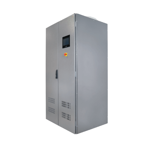
Cooling and Environmental Considerations
Static frequency converters generate heat. A 500 kVA unit at 95% efficiency dissipates 25 kW of waste heat continuously. Two cooling approaches exist:
- Air-cooled: Uses fans to draw ambient air through heatsinks. Simple and reliable but requires adequate ventilation and clean air. For dusty or corrosive environments, filter maintenance is critical.
- Liquid-cooled: Uses a water-glycol mixture to transfer heat to an external radiator or chiller. Allows higher power density and quieter operation. Common in marine, military, and high-power industrial applications.
Environmental derating applies when ambient temperature exceeds 40°C or altitude exceeds 1,000 meters. IGBT junction temperature limits require reduced current capacity under these conditions. A converter rated for 100 kVA at sea level may only deliver 85 kVA at 2,000 meters altitude unless specifically designed for high-altitude operation.
IP ratings determine protection against dust and moisture:
- IP20: Standard indoor installation, protected against finger contact.
- IP54: Dust-protected and splash-protected. Suitable for factory floors.
- IP65: Dust-tight and jet-water-protected. Required for outdoor or harsh environments.
Standards and Certifications
Compliance with industry standards is not optional for most static frequency converter applications. Buyers should verify that suppliers can demonstrate conformance to relevant standards before purchase.
Aviation Standards
- ISO 6858: Specifies dimensions, ratings, and tests for aircraft ground support electrical connectors. Ensures physical compatibility between the GPU cable and the aircraft receptacle.
- MIL-STD-704F: Defines the electrical power characteristics of aircraft in the US military. Ground power must meet Category A or B limits for voltage, frequency, phase balance, and transient response.
- GJB 572A: Chinese military standard for aircraft ground power supply equipment. Parallels MIL-STD-704F with additional domestic test requirements.
- SAE ARP 5015: Guidelines for 400Hz ground power performance at the aircraft interface.
Industrial and Grid Standards
- IEC 61000 series: Electromagnetic compatibility (EMC) requirements. Includes immunity to disturbances (surges, dips, harmonics) and limits on emitted disturbances.
- IEEE 519: Harmonic control in electric power systems. Specifies maximum voltage and current distortion levels at the point of common coupling.
- IEC 62477-1: Safety requirements for power electronic converter systems and equipment.
- CE marking: Required for products sold in the European Economic Area. Demonstrates conformity with health, safety, and environmental protection standards.
- UL 508C: US safety standard for power conversion equipment.
- CSA C22.2: Canadian equivalent to UL standards.
Shandong Electric designs static frequency converters to meet CE, IEC, and relevant military standards. Certification documentation is available for each product family upon request.
Installation and Maintenance Best Practices
Static frequency converters require less maintenance than rotary sets, but proper installation and periodic care are essential for reliable operation.
Site Preparation
Before the converter arrives, verify:
- Floor loading: Large units can exceed 2,000 kg. Confirm that the installation floor can support the weight, including seismic considerations in active zones.
- Clearance: Maintain minimum clearances per the manufacturer’s manual, typically 1 meter on all sides for air-cooled units. This ensures adequate airflow for service access.
- Ventilation: Air-cooled converters require approximately 100-150 cubic meters per minute of airflow per 100 kVA. Inadequate ventilation causes thermal derating and premature aging.
- Foundation: For units above 500 kVA, a reinforced concrete pad or vibration isolation may be required. Rotary sets typically need more substantial foundations due to vibration; static converters are more forgiving.
- Cable routing: Separate power cables from control and communication cables to reduce electromagnetic interference. Follow local electrical codes for conduit sizing and grounding.
Cable Sizing and Voltage Drop
Voltage drop between the converter and the load matters, especially for 400Hz aircraft power where the aircraft expects 115V ±3V at the receptacle. For a GPU located 50 meters from the aircraft with a 90 kVA load at 200V line-to-line:
- Load current = 90,000 / (200 × sqrt(3)) = 260A
- For 35mm² copper cable (resistance 0.524 milliohm/meter), single-phase drop = 260 × 0.000524 × 50 = 6.8V
- Percentage drop = 6.8 / 200 × 100 = 3.4%
This exceeds the typical 3% limit. Solutions include upsizing cable to 50mm², relocating the converter closer, or specifying a converter with cable drop compensation.
Annual Maintenance Checklist
Static frequency converter maintenance is minimal but not zero:
- Cooling system: Inspect and clean air filters quarterly in dusty environments. Check fan operation and bearing condition annually. Replace fans every 5-7 years as preventive maintenance.
- DC bus capacitors: Electrolytic capacitors degrade over time, typically losing 20% capacity after 10-15 years. Measure capacitance and ESR (equivalent series resistance) during annual shutdowns. Plan replacement at 80% of rated capacity.
- IGBT and semiconductor inspection: Thermal imaging during loaded operation identifies hot spots that indicate degraded connections or failing devices.
- Control system: Verify calibration of voltage and frequency sensors against a calibrated reference. Check that protection settings match the original specification.
- Connections: Torque-check power terminals annually. Thermal cycling loosens connections over time, creating resistance and localized heating.
Predictive Maintenance
Modern static frequency converters with digital monitoring enable predictive maintenance. The controller tracks operating hours, thermal history, capacitor health indicators, and fault logs. Shifts in these parameters warn of impending issues before they cause failure.
For mission-critical installations, remote monitoring via Ethernet or cellular connection allows the manufacturer’s support team to diagnose issues and recommend action without dispatching a technician.
Cost Analysis and Total Cost of Ownership
Purchase price is only part of the equation. A static frequency converter’s true cost includes capital expense, installation, energy losses, maintenance, and eventual replacement.
Capital Cost Ranges
Static frequency converter prices vary with power rating, features, and application requirements. Approximate 2026 ranges for industrial-quality units:
| Power Rating | Approximate Price Range (USD) |
|---|---|
| 10-30 kVA | 3,000−3,000−8,000 |
| 30-90 kVA | 8,000−8,000−25,000 |
| 90-200 kVA | 25,000−25,000−60,000 |
| 200-500 kVA | 60,000−60,000−150,000 |
| 500-1,000 kVA | 150,000−150,000−350,000 |
| 1,000-2,000 kVA | 350,000−350,000−700,000 |
Aviation-grade 400Hz units with aircraft interlock, cable drop compensation, and MIL-STD certification typically command a 20-40% premium over industrial 50/60Hz units of the same power rating.
10-Year TCO Worked Example
Consider a 100 kVA installation running at 75% load for 4,000 hours per year.
Static frequency converter scenario:
- Capital cost: $32,000
- Efficiency: 94%
- Annual energy loss: 75 × 4,000 × (1 – 0.94) / 0.94 = 19,149 kWh
- Annual energy cost at 0.12/kWh:∗∗0.12/kWh:∗∗2,298**
- Annual maintenance: $400 (filters, inspection)
- Major capacitor replacement at year 10: $3,000
- 10-year TCO: 32,000+(32,000+(2,298 + 400)×10+400)×10+3,000 = $61,980
Rotary converter equivalent scenario:
- Capital cost: $38,000
- Efficiency: 85%
- Annual energy loss: 75 × 4,000 × (1 – 0.85) / 0.85 = 52,941 kWh
- Annual energy cost at 0.12/kWh:∗∗0.12/kWh:∗∗6,353**
- Annual maintenance: $2,800 (bearings, brushes, alignment, lubrication)
- Major overhaul at year 7: $8,000
- 10-year TCO: 38,000+(38,000+(6,353 + 2,800)×10+2,800)×10+8,000 = $137,530
The static frequency converter saves $75,550 over 10 years, a 55% reduction in total cost of ownership. The payback period on the initial capital difference is approximately 1.2 years.
Hidden Savings
Beyond direct cost, static converters deliver additional value:
- Space savings: A 100 kVA static unit occupies approximately 0.8m²; a rotary set needs 2.5m². At 500/m2annualfacilitycost,that′s500/m2annualfacilitycost,that′s850/year saved.
- Noise reduction: Rotary sets at 75-85 dB may require acoustic enclosures or separate rooms. Static units at 55-65 dB often install in standard electrical rooms.
- Reduced cooling load: Lower energy losses mean less waste heat to remove from the building. A 10 kW reduction in heat load reduces HVAC operating cost by approximately $800/year in temperate climates.
Frequently Asked Questions
What is a static frequency converter?
A static frequency converter is an electronic power conversion system that changes AC power from one frequency to another using solid-state semiconductors, with no rotating mechanical parts. It follows an AC-DC-AC architecture: rectification, DC link filtering, and inverter-based frequency synthesis.
How does a static frequency converter work?
It works in four stages. First, a rectifier converts input AC to DC. Second, a DC link smooths and stores the DC voltage. Third, an IGBT-based inverter switches the DC at high frequency to synthesize AC output at the desired frequency. Fourth, output filters remove switching noise to deliver a clean sine wave.
Why do aircraft use 400Hz power?
Aircraft use 400Hz because higher frequency allows transformers, motors, and generators to be much smaller and lighter. At 400Hz, a transformer can be approximately 1/8 the weight of an equivalent 50Hz design. This weight reduction directly reduces fuel consumption.
What is the difference between a static and rotary frequency converter?
A static converter uses electronic switching (IGBTs) with no moving parts. A rotary converter uses a motor mechanically coupled to a generator. Static converters are more efficient, require less maintenance, are quieter, and occupy less space. Rotary converters handle heavy surge loads better and may be preferred in very dirty electrical environments.
How much does a static frequency converter cost?
Prices range from approximately 3,000fora10kVAunitto3,000fora10kVAunitto700,000 for a 2,000 kVA industrial system. A 100 kVA aviation-grade 400Hz unit typically costs $30,000-40,000. Total cost of ownership over 10 years is typically 50-60% lower than an equivalent rotary converter.
What maintenance does a static frequency converter need?
Maintenance is minimal compared to rotary sets. Annual tasks include cleaning or replacing air filters, checking fan operation, torque-checking power connections, and verifying control calibration. DC bus capacitors may need replacement after 10-15 years. IGBT modules typically last 15-20 years under normal conditions.
Can a static frequency converter change voltage and frequency simultaneously?
Yes. Most static converters can accept a wide range of input voltages and frequencies and produce a programmable output voltage and frequency. Common conversions include 400V/50Hz to 480V/60Hz, 480V/60Hz to 400V/50Hz, and utility power to 115V/400Hz for aviation.
What standards should a 400Hz GPU meet?
A 400Hz aircraft ground power unit should comply with ISO 6858 (connector standards), MIL-STD-704F or GJB 572A (power quality), and relevant EMC standards such as IEC 61000. Output specifications typically include 115V/200V, 400Hz ±0.01%, voltage regulation ±1%, and THD under 3%.
How do I size a static frequency converter for my application?
Start by identifying your load type (resistive, inductive, rectifier, or regenerative), maximum running power in kVA, inrush or surge requirements, and power factor. Add 15-20% margin for future growth. For motor loads, verify that the converter can handle starting current or implement soft-start sequencing.
Are static frequency converters more reliable than rotary converters?
For most applications, yes. The absence of bearings, brushes, and mechanical couplings eliminates the most common failure modes of rotary sets. Mean time between failures (MTBF) for industrial static converters typically exceeds 50,000 hours, compared to 20,000-30,000 hours for rotary motor-generator sets.
Conclusion
A static frequency converter is the right technology for applications that demand precise frequency control, minimal maintenance, quiet operation, and efficient power conversion. From 400Hz aircraft ground power at busy international airports to 50/60Hz industrial test systems in manufacturing plants, solid-state conversion has become the standard for new installations.
The key to a successful project is correct specification. Match the converter to your load characteristics, electrical environment, standards requirements, and physical constraints. Calculate total cost of ownership, not just purchase price. And verify that your supplier can deliver the certifications, documentation, and after-sales support your application demands.
At Shandong Electric, we design and manufacture static frequency converters from 1 kVA to 2,000+ kVA for aviation, industrial, military, and infrastructure applications. Our engineering team supports specification development, custom design, and global delivery. Whether you need a standard 400Hz GPU or a specialized high-reliability system, we can configure a solution for your exact requirements.
Ready to specify your static frequency converter? Contact our engineering team for a technical consultation, or browse our 400Hz frequency converter product range to see standard configurations.
