
A static frequency converter maintenance guide is a structured program of inspection, cleaning, testing, and component replacement designed to keep a converter operating reliably throughout its service life. Proper maintenance prevents the unplanned failures that cost industrial facilities an average of $260,000 per hour during peak production.
If you operate a static frequency converter in an airport, factory, data center, or military installation, you have probably seen the run-to-failure approach in action. Equipment runs until it stops. Then comes the emergency repair, the production delay, the flight cancellation, or the patient safety incident. This article gives you a complete maintenance schedule with checklists, troubleshooting procedures, and component replacement guidance you can put into practice immediately.
Key Takeaways
- Every dollar spent on preventive maintenance saves $4-5 in repair costs, according to US Department of Energy data.
- A complete static frequency converter maintenance program includes daily checks, weekly cleaning, monthly connection verification, quarterly insulation testing, and annual deep maintenance.
- Cooling fan failure and capacitor degradation cause 60% of static converter failures, making thermal management the highest-priority maintenance focus.
- Electrolytic capacitors lose approximately 50% of their remaining lifespan for every 10 degrees Celsius they operate above their rated temperature.
- A downloadable maintenance checklist organized by interval allows technicians to perform each task without guessing what comes next.
What Is Static Frequency Converter Maintenance?
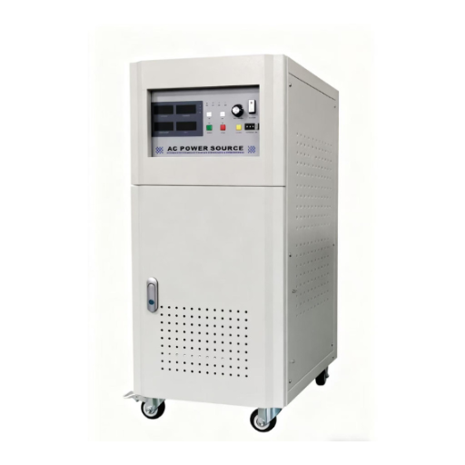
Static frequency converter maintenance is the scheduled inspection, cleaning, testing, and component replacement that keeps a solid-state power conversion system operating within specification. The converter contains no rotating parts (hence “static”), so maintenance focuses on electronic components, thermal management, electrical connections, and environmental protection rather than mechanical wear.
There are three maintenance strategies:
- Preventive maintenance: Scheduled tasks performed at fixed intervals regardless of equipment condition. This is the foundation of most maintenance programs.
- Predictive maintenance: Condition monitoring that identifies degradation before failure, allowing maintenance to be scheduled when actually needed rather than at fixed intervals.
- Condition-based maintenance: Automated monitoring with alert thresholds that trigger maintenance only when parameters exceed acceptable limits.
For most facilities, preventive maintenance is the practical starting point. Predictive and condition-based strategies can be added as monitoring technology and expertise mature.
Analyzing the cost advantage is simple. On Carnival afternoon, we’ll calculate the production frequency at $50,000 per hour. Emergency replenishment within six hours results in $50,000 per hour of production. If the replenishment continues for six hours, each person receives $300,000. This panne could be fully replenished for $2,000 per hour, sufficient to replace the refrigerated ventilator before it is sold. The replacement of the ventilator would represent 0.06% of the total price of the panne.
Maintenance Schedule by Interval
Daily Checks (5-10 Minutes)
Daily checks are visual and sensory. They require no tools and should be performed by the operator at the start of each shift.
- Verify all status indicators show normal operation (green LED, no fault codes).
- Listen for abnormal sounds: buzzing, clicking, or grinding from cooling fans.
- Check for unusual odors: burning plastic, ozone, or hot electrical smell.
- Record operating parameters on the log sheet: output voltage, output frequency, load current, and enclosure temperature.
- Verify cooling air is flowing from exhaust vents.
A daily check at a European airport ground power station caught a fault code indicating reduced fan speed on a Monday morning. The technician scheduled a fan replacement for the next scheduled maintenance window on Wednesday. The converter continued operating at reduced load until the replacement. Without the daily check, the fan would have failed completely during the Friday evening departure peak.
Weekly Checks (15-20 Minutes)
Weekly checks extend daily observations with light cleaning and physical inspection.
- Clean external enclosure surfaces and ventilation openings with a soft cloth or brush.
- Remove and inspect air filters. Clean with compressed air if dirty; replace if damaged or excessively clogged.
- Inspect all visible cable connections for looseness, discoloration, or heat damage.
- Verify ground connection integrity at the main ground terminal.
- Check that enclosure doors and seals close properly.
Monthly Checks (30-45 Minutes)
Monthly checks require basic tools and should be performed by a qualified technician.
- Tighten all power and control terminal connections to manufacturer-specified torque values using a calibrated torque screwdriver. Loose connections generate heat and are a leading cause of electrical fires.
- Clean heat sink fins with dry compressed air directed from the clean side toward the dirty side. Never use wet cleaning methods on energized or recently de-energized equipment.
- Inspect each cooling fan for vibration, bearing noise, or reduced airflow. Note any fan that sounds different from the others.
- Visually inspect DC bus capacitors for bulging, leaking electrolyte, or discoloration. Any capacitor showing these signs must be replaced immediately.
- If thermal imaging equipment is available, record temperatures at key points: heat sinks, terminal blocks, and enclosure surfaces.
Quarterly Checks (1-2 Hours)
Quarterly checks require test equipment and more technical expertise.
- Measure insulation resistance of power circuits using a 500V or 1000V megohmmeter. Minimum acceptable value is 1 MΩ per kV of rated operating voltage.
- Test all emergency stop circuits and protective relay functions. Verify that overcurrent, overvoltage, undervoltage, and overtemperature protections operate correctly.
- Verify output voltage and frequency accuracy using a calibrated digital multimeter and frequency counter. Compare against specification tolerances.
- Inspect input and output filter assemblies for dust accumulation and connection integrity.
- Review the converter fault history log. Any recurring fault code indicates an underlying problem that requires investigation.
Annual Maintenance (4-8 Hours)
Annual maintenance is a comprehensive service that may require planned downtime.
- Replace all cooling fans, even if they appear to be operating normally. Fan bearing life is typically 30,000-50,000 hours; beyond this range, failure probability increases sharply.
- Replace all air filters with new units.
- Test and calibrate all protection relays, sensors, and metering circuits against known reference values.
- Perform deep cleaning of the entire enclosure interior using vacuum and dry compressed air. Remove all dust from control boards, power modules, and filter assemblies.
- Conduct a full-load test run lasting at least 30 minutes while recording all operating parameters. Compare results to baseline data from commissioning or the previous annual maintenance.
- Update control firmware if the manufacturer has released updates that address known issues or improve functionality.
- Document all measurements, replacements, and observations in the maintenance record.
| Interval | Tasks | Time | Skill Level |
|---|---|---|---|
| Daily | Visual inspection, parameter logging | 5-10 min | Operator |
| Weekly | External cleaning, filter inspection | 15-20 min | Operator |
| Monthly | Torque check, heat sink cleaning, capacitor visual | 30-45 min | Technician |
| Quarterly | Insulation test, protection relay test, accuracy check | 1-2 hours | Technician |
| Annual | Fan/filter replacement, deep clean, full-load test | 4-8 hours | Technician |
Component Replacement Procedures
Cooling Fan Replacement
Cooling fans are the most frequently replaced component in a static frequency converter. Proper replacement ensures continued thermal management.
- Lock out and tag out all power sources to the converter. Verify zero energy with a multimeter.
- Allow 5 minutes minimum after power removal for DC bus capacitors to discharge through internal bleed resistors.
- Remove the fan retaining screws or clips. Note the airflow direction marked on the fan housing.
- Disconnect the fan power connector. If the connector is polarized, note the wire colors or terminal positions.
- Install the replacement fan with the same airflow direction. Reverse airflow reduces cooling efficiency by 30-50%.
- Reconnect the power connector and secure the fan.
- Restore power and verify the fan operates at correct speed with proper airflow direction.
DC Bus Capacitor Replacement
Capacitor replacement requires strict safety procedures because DC bus capacitors store lethal energy even after power removal.
- Lock out and tag out all power sources.
- Wait a minimum of 5 minutes after power removal. Some large converters require 10-15 minutes for full discharge.
- Verify zero voltage across the DC bus terminals with a properly rated multimeter.
- Short the capacitor terminals with an insulated discharge tool to ensure complete discharge.
- Photograph the capacitor orientation and terminal connections before removal.
- Remove the retaining hardware and extract the capacitor. Note that large capacitors can weigh 5-10 kg.
- Test the replacement capacitor with a capacitance meter or ESR meter before installation.
- Install the new capacitor with correct polarity. Reverse polarity on an electrolytic capacitor causes immediate failure and possible explosion.
- If the capacitor has been in storage for more than 12 months, perform a reforming procedure: apply 50% rated voltage for 30 minutes, then 75% for 30 minutes, before applying full voltage.
- Reassemble and restore power. Monitor the capacitor temperature for the first 2 hours of operation.
Air Filter Cleaning and Replacement
Air filters protect internal components from dust that acts as a thermal insulator and can cause conductive paths on circuit boards.
- Remove the filter from its housing without allowing trapped dust to fall into the enclosure.
- Assess the filter condition. Filters that are torn, oil-soaked, or structurally damaged must be replaced rather than cleaned.
- Clean reusable filters with compressed air directed from the clean side. For heavy contamination, wash in warm water with mild detergent and dry completely before reinstalling.
- Inspect the filter sealing surfaces. Damaged seals allow bypass airflow that reduces filter effectiveness.
- Reinstall the filter with correct orientation. Most filters have a directional arrow indicating proper airflow direction.
IGBT Module Inspection (Non-Replacement)
IGBT (Insulated Gate Bipolar Transistor) modules are the power switching devices at the heart of the converter. Replacement requires factory-level expertise, but inspection identifies problems before catastrophic failure.
- Visually inspect the module for burn marks, cracks in the housing, or discoloration of the thermal interface material.
- Check the gate drive connection integrity. Loose gate drive connections cause switching anomalies that destroy the module.
- Inspect the thermal grease or pad between the module baseplate and heat sink. Dried or cracked thermal interface material increases thermal resistance and causes overheating.
- If abnormal conditions are found, document with photographs and contact the manufacturer or authorized service provider. Do not attempt IGBT module replacement without proper training and equipment.
Troubleshooting Common Faults
Overheating Faults
Symptoms: High temperature alarm, thermal shutdown, reduced output capacity.
Causes: Blocked ventilation openings, failed or degraded cooling fan, dirty heat sinks, excessive ambient temperature, failed thermal sensor.
Resolution steps:
- Check all ventilation openings for blockage by dust, debris, or stored items.
- Verify each cooling fan operates at rated speed. Replace any fan not operating correctly.
- Clean heat sink fins with compressed air.
- Verify ambient temperature is within converter specification. If the installation environment exceeds 40°C consistently, consider additional cooling or relocation.
- If the fault persists after these steps, the thermal sensor may require calibration or replacement.
Output Voltage or Frequency Deviation
Symptoms: Load equipment malfunction, alarm codes indicating output parameter out of tolerance.
Causes: Input voltage fluctuation outside acceptable range, control board fault, output filter degradation, incorrect parameter settings.
Resolution steps:
- Measure input voltage and frequency. Verify they remain within the converter input tolerance range.
- Check converter parameter settings against the commissioning documentation. Incorrect output frequency or voltage settings are a common cause of this fault.
- If input and parameters are correct, inspect the output filter assembly for damaged capacitors or inductors.
- If the filter is intact, the control board may require diagnosis by the manufacturer.
Overcurrent and Short Circuit Faults
Symptoms: Immediate shutdown, blown fuses, IGBT failure indication.
Causes: Load-side short circuit, motor or cable insulation failure, incorrect overload parameter setting, IGBT module failure.
Resolution steps:
- Disconnect the load and measure load-side insulation resistance with a megohmmeter.
- Check load cables for physical damage or pinched conductors.
- Verify overload parameter settings match the actual load characteristics.
- If load and parameters are correct, the converter output stage requires professional diagnosis. IGBT module testing requires specialized equipment.
Ground Faults
Symptoms: Insulation fault alarm, earth leakage trip.
Causes: Cable insulation breakdown, moisture ingress, component failure, creating a path to ground.
Resolution steps:
- Disconnect all load cables and test each conductor to ground with a megohmmeter.
- If cable insulation is intact, test converter output terminals to ground with power removed.
- Inspect the enclosure for moisture, condensation, or water ingress. Install a space heater or dehumidifier if condensation is recurring.
- If the fault is internal to the converter, contact the manufacturer for service.
| Fault Code | Symptom | Likely Cause | First Action |
|---|---|---|---|
| Over Temperature | Thermal shutdown | Blocked cooling or failed fan | Check ventilation and replace fan if needed |
| Over Voltage | Input surge protection | Grid voltage spike | Verify input power quality |
| Under Voltage | Low input voltage | Grid sag or loose connection | Check input connections |
| Over Current | Load side fault | Short circuit or overload | Isolate load and test insulation |
| Ground Fault | Insulation alarm | Moisture or cable damage | Perform an insulation test |
| Fan Fault | Cooling alarm | Fan failure or blockage | Replace or clean the fan |
| Output Error | Parameter deviation | Filter or control fault | Verify settings and inspect filter |
400Hz Aviation Ground Power Specific Maintenance
Static frequency converters used for 400Hz aviation ground power operate in a unique environment that demands additional maintenance attention.
MIL-STD-704 compliance verification should be performed during annual maintenance. The output voltage regulation, frequency stability, and transient response must meet the applicable aircraft category requirements. Any deviation indicates degradation of the output filter or control system.
Aircraft connector inspection is critical because the connection interface experiences frequent mating cycles, weather exposure, and occasional rough handling. Inspect connector pins for wear, corrosion, and proper alignment. Clean contacts with approved contact cleaner.
Flight line cable management requires special attention. Cables must be protected from aircraft movement, ground service vehicles, and jet blast. Inspect cable armor, strain reliefs, and connector backshells monthly.
Rapid thermal cycling is more severe for aviation converters than for industrial units. A converter that powers aircraft for 30 minutes, then cools for 2 hours, then powers another aircraft experiences thermal expansion and contraction hundreds of times per month. This accelerates connection loosening and solder joint stress. Quarterly torque verification is essential.
EMCON mode testing should be performed during annual maintenance for military applications. Verify that the converter operates within specified acoustic and electromagnetic emission limits when operating in Emissions Control conditions.
Predictive Maintenance and Condition Monitoring
Modern static frequency converters can integrate sensors that monitor operating parameters continuously. This data enables maintenance to be scheduled based on actual condition rather than fixed intervals.
Temperature trending is the most valuable predictive indicator. Gradual increases in heat sink or component temperature indicate increasing thermal resistance, often from dust accumulation, fan degradation, or thermal interface material aging.
Vibration analysis for cooling fans identifies bearing wear before the fan fails. A fan with bearing wear typically shows increased vibration amplitude at the bearing rotational frequency.
Harmonic analysis of the output waveform reveals filter degradation. Changes in total harmonic distortion or individual harmonic amplitudes often indicate capacitor aging or inductor saturation.
Infrared thermography during quarterly inspections identifies hot spots that are invisible to visual inspection. A connection that is 20°C hotter than adjacent connections is failing and requires immediate attention.
For facilities with multiple high-reliability frequency converter systems, integrating condition monitoring with a centralized maintenance management system provides fleet-wide visibility and enables maintenance resources to be deployed where they are most needed.
Spare Parts and Inventory Recommendations
Maintaining a spare parts inventory reduces repair time from days to hours. The recommended inventory depends on the number of converters in service and their criticality.
Critical spares (keep on-site for immediate replacement):
- Cooling fan assemblies: One spare per 5 converters, minimum 2 spares
- Air filters: One full set per converter (minimum 6-month supply)
- Power fuses: One complete set per converter size
- Control board: One spare per converter model (if multiple units share a model)
Important spares (obtain within 1-2 weeks):
- DC bus capacitors: One set per 10 converters
- IGBT driver boards: One per converter model
- Power contactors: One per converter size
Long-lead items (plan 8-12 week procurement cycle):
- Main IGBT power modules
- Custom magnetic components (transformers, inductors)
- Enclosure assemblies
For military aircraft ground power supply applications, the procurement cycle for some components can extend to 16-20 weeks due to specification and qualification requirements. Military maintenance programs should maintain larger on-site inventories.
Maintenance Record Keeping
Accurate maintenance records support warranty claims, regulatory compliance, and trend analysis.
Each maintenance entry should include:
- Date and time of service
- Technician name and qualification level
- Tasks performed
- Measurements recorded (temperatures, insulation resistance, voltage, frequency)
- Components replaced, with part numbers and serial numbers
- Anomalies found and corrective actions taken
- Next scheduled maintenance date
For aviation and healthcare applications, maintenance records may be required for regulatory audits. Retain records for the service life of the equipment plus any regulatory retention period.
Digital maintenance management systems simplify record keeping and enable trending analysis. However, a paper logbook at each converter location provides immediate access during inspections and ensures continuity if the digital system is unavailable.
Conclusion
A static frequency converter maintenance guide is only valuable when it is followed consistently. The schedule, procedures, and checklists in this article are designed to be practical for real maintenance teams with real time constraints.
The principle is simple: daily checks catch problems early, monthly maintenance prevents degradation, and annual service extends converter life. The alternative is emergency repair at 3:00 AM during a production peak or a flight departure rush.
Every dollar invested in preventive maintenance returns four to five dollars in avoided repair costs and downtime. The fan you replace today during a scheduled shutdown costs 180.Thesamefanthatfailsnextmonthduringanunplannedoutagecosts180.Thesamefanthatfailsnextmonthduringanunplannedoutagecosts180 plus $50,000 in lost production.
Ready to implement a professional maintenance program for your static frequency converters? Contact Shandong Electric for maintenance contracts, spare parts kits, and field service support tailored to your converter fleet and operational requirements.
